background image

Summary of Contents for 425101

Page 1: ... THIS PRODUCTBE ASSEMBLEDBY TWOPERSONS TO AVOIDPOSSIBLE INJURY KEEP ALL FRAMECONNECTIONS LOOSE UNTIL INSTRUCTEDIN THE ASSEMBLY STEP SEQLrENCESTO SECURELYTIGHTEN IF YOUEXPERIENCE ANYPROBLEMWITH THE ASSEMBLY OF THIS PRODUCT PLEASE CONTACTYOUR DEAL OR YOURPARABODY CUSTOMER SERVICE REPRESENTATIVE AT 1 800 328 97 I4 TOOLSREQUIRED RATCHET 3 4 SOCKET or WRENCH 9 16 SOCKET or WR NCH 7 16 SOCKET or WRENCH ...

Page 2: ... A TTENTtON _U_NL ES_S__Q HE L L _C_Q_NNE TI N L N I T F__ _O_N_ WAS BOLT LOCKNUT NOTE BOLTLENGTHI MEASURED FROMTHEUNDERSIDE OF THE HEADOF THE BOI T BOLT LENGTH BOLT LENGTH RULER ...

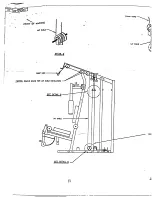
Page 3: ...1 03 PRESS SUPPORT TUBE 6 9 3 1 X1 IN PULLEY 3116201 7 1 Insert two 2 1 2 IN FLANGE BEARINGS into the SWIVEL PULLEY BRACKET as shownon drawing Assemble theSWIVEL PULLEY BRACKET to thePRESS BASE as shown ondrawing using ore I I X 4 IN BOLT two 2 I 2 IN WASHERS and one I I 2 IN LOCKNUT frIGHTEN THE CONNECTION ENOUGH REMOVETHE PLAY YET ALLOWING THE SWIVEL BRACKET TOROTATE FREELY 3 SECURELY assemble o...

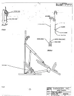
Page 4: ...ERS and one I 1 2 IN LOW HEIGHT LOCK NUT o SECURELY assembleone I 3 1 X1 IN PULLE re tbe r gnt flat of the BASE as shownon awing using one 1 3 g X 2 IN BOLT one 1 CABLE RETAINING CLIP one 1 31g IN WASHER and one I 3 1 IN LOCK SECURELY assemble two 2 3 1 2 XI IN PULLEYS to the middle fiat of the BASE as shownin ETAIL B using one I 3 8 X 4 1 IN THREADED STUD two 2 CABLE RETAINING CLIPS and two 2 3 8...

Page 5: ...31 g IN LOCK NUT SECURELY assemble one I 31gX 2 3 4 IN BOLT two 2 318IN WASHERS andone I 318IN LOCK NUT FRONT UPRIGHT inthehole above thepullsy assembled inSTEP 4 SECURELY assemble one I 318IN SPRING PINASSEMBLY to the SPRING PINHOUSING of the FRONT UPRIGHT as shownin DETAILA IllIMPORTANT TIGHTEN THENUT OF THESPR ING ASSEMBLY SECURELY o 10 A tach one I THUMBSCREW to theFRONT UPRIGHT as shown on dr...

Page 6: ...EYS one 1 4 I 2 X1 IN PULLEY to the inside ofthe TOP as shown in DETAIL A using three 3 3 8 X2 3 4 IN BOLTS one 1 318X2 II4 IN BOLT six 6 3 8 IN SPACERS two 2 318 IN WASHERS and four 4 3 8 IN LOCK NIYI S 2 _ LOOSELY resemble the TOPBOOM to the top ofthe REAR MIDDLE and FRONT UPRIGHTS as shownon oh awing using four 3 8 X3 IN BOLTS two 2 I X3 IN BOLTS eigh t 8 3 8 IN WASHERS three 3 I 2 IN one I I 2...

Page 7: ...f the LEG CURL EXTENSION AR I pull back the SPRING PIN and Insert the ADJUSTABLE ROLLER PADSLEEVE as shownin DETAIL E Release the SPKI NG PINinto one of the adjustmentholes andreinsert the 2 IN SQ END CAP Assemblethe two 2 ROLLER PADS to the LEGCURL EXTENSION ARM as shownon drawing using one I ROLLER PADSHAFT two 2 PLASTICWASHERS and two 2 9 I 6 MUSHROOM CAPS MAKESURE THE ROLLERPAD SHAFT IS INSERT...

Page 8: ...5 PAD IS ira X10 1 2 6457301 1 I Inse t the PUSH PULL CABLE through the bottom oftheRRESSARM up to the CONTROL LEV R as shownin DETAIL A and hold in pla e with one 1 E RING 2 SECURELY assemble the PUSH PULL CABLE to the CONTROL LEVER as shownin DETAIL A using one 1 IN JOINTCONNECTOR CAP one I 8 INT TOOTH LOCK WASHER and one 1 8 32 X 3 16 IN SCREW Slide one I IN VI NYL SL EEVE ov er th e CO NTROL L...

Page 9: ...Assemble the PUSH PULL CABLE to the SPRINGPIN HOUSING and to the L BRACKET on fl e RECEIVING TUBE as shown in DETAIL D using the f ollowing steps Threadthe first I 4 2 i IN NUT to the bottomof the threadedendof the CABLE Allow other I 4 28 IN NUT to hangloose on the exposedCABLE until the SPRING PINASSEMBLY is attached Securely assemble the SPRING PIN ASSEMBLY to the SPRING PIN BARREL IMPORTANT TI...

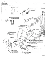
Page 10: ...NTER PULLEY BRACKET 6 30203 BEARING HOUSING 6 9601 I 6 LEFT PEC ARM 6ff 97__O 1 7 RIGHT PEC ARM L 6529801 I 8 BACK PAD 6433701 J 1 9 SEAT PAD 64 3 01 1 10 3 1 2 XI IN PULLEY 3116201 l I 4X 12 IN ROLLER PADS 61 6 01 I Pre assemble thePRESS BACK SUPPORT using thefollowing s eps Attach eight 8 PARAGLIDE STRIPS to thePRESS BACKSUPPORT as shown in DETAIL A using thtfollowing steps Thoroughly clean all ...

Page 11: ...OR PLATES ON THE BEARING HOUSINGANDTHE CENTER PULLEY BRACKETHAVE SLOTTEDHOLES SHIFT THE BEARINGHOUSINGDOWN ANDTHE CENTERPULLEY BRACKETUP AS FAR AS POSSIBLE o Assemble two 2 3 4IN THRUST WASHERS andtwo 2 PECCAMSto theLEFTandRIGHT FECARMS as shown ondrawing Insert four 4 3 4 IN FLANGE BEARINGS into the BUSHINGS of the BEARING HOUSING as shownon drawing ll Insert theLEFTandRIGHTPECDECARMSthrough the3...

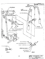
Page 12: ... two 2 PULLEY connections from the SECOND STEP 2 To assemblethe LAT CABLE follow the cable routing diagram ondrawing and use the following st ps Attach one I SNAP LINK totheball endoftheLATCABLE Remove thetwobolts in theFRONT UPRIGHT andTOPBOOMconnection RoutetheLATCABLEas shownon drawing andin DETAIL B REMOVE PULLEYS FOREASE INSTALLATION RuntheLATCABLE through thehole ofthe D RING asshown in DETA...

Page 13: ...ps Attach one 1 SNAP LINK to the ball end of the ABCABLE Insert the threaded end of the ABCABLE betweenthe top of the ABPULLEY and the BOLT in the FRONT UPRIGHT LOOSELY assemble the PULLEY BRACKETto the ABCABLE as shownin drawing Osing two 2 I 4 IN WASHERS and two 2 1 4 28 IN NUTS LOCATEPULLEY BRACKET HALFWAY UP ON THREADS OF THE AB CABLE DO NOTTIGHTENN UTS AT THIS TIME Make aloop with the ABCA IL...

Page 14: ...E mdthe LAT CABLE over the THREADED SHAFT on the BASE and slip the end of the SWIVEL for the M UTLI PRESS CABLE over the BOLT on the BASE a shownin drawing 4 SECURELY attach three 3 3 8 IN LOCK NUTS to the THREADED SHAFT and he BOLT from the previous step SECURELY tighten any loose BOLT connections madeto this point SECURELY attach the FRONT and the REAR SHROUD to the BASE and the TOPBOOM using ei...

Page 15: ......

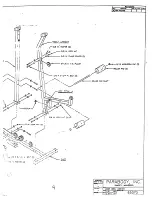
Page 16: ... DETAIL A DETAIL E DETAILD PARAE ODY INC ...

Page 17: ... i ...

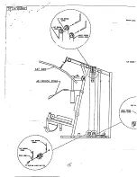
Page 18: ...DETAILE c SEE D AIL B ETA L A ...

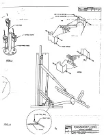
Page 19: ...DETAIL B DETAIL F WEIGNT STACK GUIDE RODS WEIGHTPLATI LEVEL 3 ...

Page 20: ......

Page 21: ...L_ATBAR CRUNCH ...

Page 22: ... ...

Page 23: ... SHOWN f L CURL EXT SlON CRUNCH FRONTOF MACH N IP D D t I I I ...

Page 24: ... I I I t PARABODY INc 42 9101 ...

Page 25: ......

Page 26: ... PARABODY INC I Y I NII i A _ Y IN T 1 ...

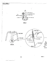
Page 27: ...DETAIL ...

Page 28: ... _ L PARABODY INC R Y ...

Page 29: ... RECEIVING SEE DETAIL LEVEL ...

Page 30: ...DETAILC DETAIL I 1 I I I I I I __ PARAt3ODY INC ...

Reviews: