background image

Post-Installation Checks and Testing

Post-Installation Checks

14

MMR2 Installation and Service Manual


Ver 1

2.1.1   Preliminary Tools and Materials

• 1x Small flat-blade screw driver (for wire terminal blocks)
• 1x Medium Phillips screw driver (for circuit board mounting screws)
• 1x Digital Multimeter {DMM} (with Low Resistance range or “Continuity” function)

2.1.2   Preliminary MMR2 Hardware Check 

Make sure the white wires from the card readers are properly connected to the white wires of the 

Tamper-Detect switch in the mounting collar or box. Make sure the card reader is properly seated in its 

mounting collar or box and the Tamper-detect switch “finger” is depressed. 

Door Sense Jumper (JP1)

Near coin-cell battery and Maintenance

Mode push-button. Sets the Door Sense

to normally-closed (NC) when in place.

Jumper in place on Door Sense terminal 

block and on JP1.

Egress (Exit) Switch Input

Input opens door (activate door relay) for 

selected amount of time.

Normally-Closed (NC); with jumper

across the terminal block when Exit

switch is not required.

Egress Activation Time

Delay time for an active door-control relay

after an Egress switch is activated.

5 seconds

Door Override Input

Activates door-control relay(s).

Normally-Closed (NC); with jumper

across the terminal block when Door 

Override output signal is absent.

Holiday Schedule

Standard holiday schedule file for current

years (or next year).

Standard Holiday Schedule in place

Port Number Value

Internet port number value

Port 2000

Sensor Configuration 

Mapping

Allows configuration of Outputs 1 & 2 (and

I/O Relay Outputs), assignment of Card

Reader alerts, I/O Inputs, and Inhibit functions.

All assignments are blank

Suspect Card BIN File

System expects: 9999999999999999 string in

Stolen Card Binfile or Controller will lock up

after first card-read.

9999999999999999 in Stolen Card Binfile

Suspect Card Function

Controller scans up to 50 stolen or

“suspected” cards from a small Binfile, locks

down the Card Reader(s) and door control

relay(s) when a suspected value is detected.

Not selected/activated

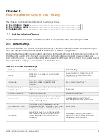
TABLE 2–1.  Controller Default Settings

Function

Description

Default Settings

Summary of Contents for MMR2

Page 1: ...Parabit Systems Inc MMR2 Installation and Service Manual Release Version 1 3 Parabit Systems Inc 35 Debevoise Avenue Roosevelt NY 11575 October 2019...

Page 2: ...E Copyright 2019 by Parabit Systems Inc All rights reserved No part of the contents of this book may be reproduced or transmitted in any form or by any means without the written permission of the publ...

Page 3: ...lation 5 Overview 5 MMR2 Install Diagrams 5 Electrical Installation 8 MMR2 Wiring 8 Wiring the Card Readers and Basic Input Devices 8 ACS 1EUL Card Reader and Input Device Wiring 10 Chapter 2 Post Ins...

Page 4: ...Table of Contents ii This page intentionally left blank...

Page 5: ...tested and found to comply with the limits for a Class B digital device pursu ant to Part 15 of the FCC Rules These limits are designed to provide reasonable protection against harmful interference i...

Page 6: ...information Convention Example Screen names dialog box names tab names window names field names and menu names appear in bold font Click the Customer box File names are italicized AxsView Transceiver...

Page 7: ...eader To return to your previous location in the manual after following a hyperlink press Alt Left Arrow To return to the hyperlink destination after returning to the previous location press Alt Right...

Page 8: ...Preface 4 MMR2 Installation and Service Manual Ver 1 This page intentionally left blank...

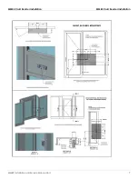
Page 9: ...Installation 5 1 2 Electrical Installation 8 1 1 MMR2 Card Reader Installation 1 1 1 Overview The MMR2 uses Near Field Communication NFC to read contactless EMV cards and mobile devices as well as ma...

Page 10: ...r Installation MMR2 Card Reader Installation 6 MMR2 Installation and Service Manual Ver 1 Note Although the diagrams reference SkimGard IMSR readers these diagrams should be used for MMR and MMR BT in...

Page 11: ...MMR2 Card Reader Installation MMR2 Card Reader Installation MMR2 Installation and Service Manual Ver 1 7...

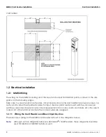
Page 12: ...dditional power sources cor rectly and to label the sheathed cables for input devices card readers exit switches door sense switches sensor devices and output devices electrical door locks alarm contr...

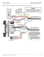
Page 13: ...Electrical Installation MMR2 Card Reader Installation MMR2 Installation and Service Manual Ver 1 9 Note The wiring diagram below applies to both the ACS 1E and ACS 1EUL...

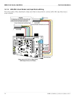
Page 14: ...Electrical Installation 10 MMR2 Installation and Service Manual Ver 1 1 2 1 2 ACS 1EUL Card Reader and Input Device Wiring The other ends of the sheathed cables and their connection to various ACS 1EU...

Page 15: ...Electrical Installation MMR2 Card Reader Installation MMR2 Installation and Service Manual Ver 1 11 The wiring configuration for the Second card reader board is similar to that of the Controller...

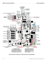
Page 16: ...MMR2 Card Reader Installation Electrical Installation 12 MMR2 Installation and Service Manual Ver 1 ACS 1EUL System with Input Output Sockets and Terminations...

Page 17: ...in the table below TABLE 2 1 Controller Default Settings Function Description Default Settings BIN Files NYCE list of acceptable magnetic card numbers Inserted in ACS 1E memory for both card reader fi...

Page 18: ...osed NC with jumper across the terminal block when Exit switch is not required Egress Activation Time Delay time for an active door control relay after an Egress switch is activated 5 seconds Door Ove...

Page 19: ...ight indicator Amber Light Insert Card Green Light Door Unlocked Red Light Door Locked b Screws Parabit provided security torque screws must be used Note NEVER use power tools to tighten Card Reader s...

Page 20: ...Post Installation Checks and Testing Post Installation Testing 16 MMR2 Installation and Service Manual Ver 1 2 2 1 Main Card Reader Tests...

Page 21: ...martphone with a digital wallet installed containing one active credit card When planning to perform an MMR2 skim test a device that operates as an NFC reader is required Begin by turning on the ACS 1...

Page 22: ...ck out mode will not accept any cards Solid amber card accept mode see below Green on schedule open If the reader is amber and not reading cards remove and wire the reader directly to the con troller...

Reviews: