background image


34

7.1. 

Battery Replacement Procedure 

(QUALIFIED SERVICE PERSONNEL ONLY)


This UPS system does not have Hot-swappable batteries. The UPS system 
must be turned Off to perform the Battery Replacement. 

7.1.1 

Turn Off all the equipment that is connected to the UPS. 

7.1.2 

Press the Off switch on the front panel of the UPS for approximately 5-

seconds. 

7.1.3 

Turn the input circuit breaker on the rear panel of the UPS to the Off 

position. 

7.1.4 

Turn the utility power circuit breaker at the service panel to the Off position. 

7.1.5 

Disconnect all of the communications and network cables from the rear 

panel of the UPS. 

NOTE: 

If you are using an External Battery Pack, turn ALL of the DC circuit breaker 

(s) on the rear panel of the Battery Pack (s) to the Off position. Disconnect the all of 
the battery cables from the UPS and the Battery Pack (s) rear panels. 
7.1.6 

Remove the retaining screws for the top cover on the rear panel of the 

UPS. 

7.1.7 

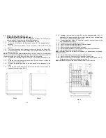
Slide the top cover towards the rear of the UPS and lift up to remove the 

top cover and set aside. (FIG. 1) 

7.1.8 

Remove the retaining screws for the side panels on the rear panel of the 

UPS. 

7.1.9 

Slide the side panels towards the rear of the UPS and lift up to remove the 

side panels and set aside. (FIG. 2) 


  FIG. 1  


      FIG. 2


35

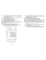
7.1.10  Looking from the front of the UPS on the right-hand side (FIG. 3), 

disconnect the battery positive (Red) wire. Place a piece of electrical tape 
over the end of battery positive (Red) wire. 

7.1.11  Disconnect battery jumper “A” and place a piece of electrical tape over the 

end of battery jumper wire “A”. 

7.1.12  Disconnect all of the battery jumper wires. 
7.1.13  Remove the battery-retaining bracket retaining screws. 
7.1.14  Remove the battery-retaining brackets. 
7.1.15  Remove the defective batteries and set aside. 
7.1.16  Install the new batteries in the same position as the original batteries. 
7.1.17  Re-install the battery-retaining brackets. 

NOTE: DO NOT

 pinch the battery wires between the batteries and the battery-

retaining brackets. 
7.1.18  Re-install the battery-retaining bracket retaining screws. 
7.1.19  Observer polarity. Reconnect all of the battery jumper wires. 
7.1.20  Remove the piece of electrical tape from the end of battery jumper wire “A”. 

Observer polarity. Reconnect battery jumper wire “A”. 

NOTE: DO NOT

 Reconnect the battery positive (Red) wire at this time.


FIG. 3 

Summary of Contents for Minuteman ED10000T

Page 1: ...Inc 1455 LeMay Drive Carrollton TX 75007 Phone 1 972 446 7363 Fax 1 972 446 9011 Internet minutemanups com UPS Sizing sizemyups com PN 34000356 R3 ED10000T ED10200T Parallel Redundant ON LINE SERIES U...

Page 2: ...Storage instruction 12 3 4 Installation of the Castor Covers 13 3 5 Wiring the Input and Output Connections 14 3 6 Operation and Setup Instructions 19 4 Communication Port EPO Port and Option Cards 30...

Page 3: ...tteries 1 1 12 CAUTION A disconnect switch must be provided by the user for the AC output circuit when the UPS s output is hardwired To reduce the risk of fire connect only to a circuit provided with...

Page 4: ...the UPS for remote control and monitoring 2 2 4 These UPS systems can be used in a Parallel Redundant application To operate these UPS systems in the Parallel Redundant mode requires the Parallel Redu...

Page 5: ...2 Er06 Output Short Circuit 33 Er08 DC Bus high voltage level abnormal 34 Er09 DC Bus low voltage level abnormal 35 Er10 Inverter Over current 36 Er11 UPS Overheated 37 Er12 Inverter Overload 38 Er13...

Page 6: ...9 2 4 Controls and Indicators 2 4 1 UPS Control panel A LCD Display B N 1 green LED illuminates when the UPS is operating in the Parallel Redundant mode C Bypass green LED illuminates when the bypass...

Page 7: ...d by a qualified person If the package is deemed to be not usable immediately contact the freight carrier and the place of purchase USE CAUTION This UPS system is extremely heavy Always use the approp...

Page 8: ...000m 0 to 50 000 ft 3 3 Storage Instruction For extended storage with moderate climates the batteries should be charged for 12 hours every 3 months Repeat this procedure every 2 months under high temp...

Page 9: ...to the terminal blocks 3 5 1 1 1 OUTPUT connections for ED10000T Hardwired only Configurations 1 7 are for Hardwiring the output of ED10000T A Qualified Electrical Contractor must perform the hardwir...

Page 10: ...KVA max load per circuit and one 208VAC 10KVA circuit Total combined output load not to exceed 10KVA 1 Connect a jumper wire from L22 to N21 2 Circuit1 120VAC L22 Line N22 Neutral G2 Ground 3 Circuit2...

Page 11: ...to terminal G2 A Qualified Electrical Contractor must perform the hardwiring The outputs must be connected to an over current protection device circuit breaker of 50 amperes in accordance with the Nat...

Page 12: ...may be used immediately but the On Battery runtime maybe less than normally expected NOTE If the UPS is going to be out of service or stored for a prolonged period of time the batteries must be recha...

Page 13: ...ypass Input Drawing J Frequency from Utility Input Drawing K Frequency from Bypass Input Drawing L UPS Output Voltage Drawing M UPS Output Frequency Drawing N UPS Output Load Drawing O UPS Battery Vol...

Page 14: ...eck the UPS settings Drawing Q1 Buzzer audible alarm Drawing R1 Self test Drawing S1 Bypass Voltage Window Drawing T Output Frequency Synchronization Window Drawing U Inverter Output Voltage Drawing V...

Page 15: ...econds and then release the audible alarm will sound 2 beeps the LCD display screen shows as drawing Q1 then the UPS is under setting mode 3 6 5 2 Except for the Buzzer as drawing Q1 Q2 and the Self t...

Page 16: ...r on the rear panel of the Battery Pack 3 6 7 4 The UPS is OFF 3 6 7 5 To completely de energize the UPS disconnect the battery cable from the rear panel of the UPS Turn Off the utility circuit breake...

Page 17: ...on Wait for approximately 1 minute until the fans turn off then turn the input circuit breaker to the On position The UPS will be in the Bypass mode Press the On switch on the front panel for 2 beeps...

Page 18: ...er of the UPS The UPS should be unlocked but the original problem may not be resolved Call for Service 33 7 Replacing the Batteries QUALIFIED SERVICE PERSONNEL ONLY Please read all of the WARNINGS and...

Page 19: ...ining screws for the side panels on the rear panel of the UPS 7 1 9 Slide the side panels towards the rear of the UPS and lift up to remove the side panels and set aside FIG 2 FIG 1 FIG 2 35 7 1 10 Lo...

Page 20: ...37 7 1 32 Back to the right hand side of the UPS FIG 3 remove the piece of electrical tape from the end of battery positive Red wire Observer polarity Reconnect the battery positive Red wire NOTE Some...

Page 21: ...oltage let through as a percentage of an applied ANSI C62 41 Cat A 6KV 5 Noise Filter Normal and common mode EMI RFI suppression Audible Noise at 1 m 3 ft 50dB 160 280VAC at loads 50 of the rated capa...

Page 22: ...m the nearest authorized service center Replacement parts and warranty labor will be borne by Para Systems For equipment located outside of the United States and Canada Para Systems only covers faulty...

Page 23: ...Name Para Systems Inc MINUTEMAN UPS Manufacturer s Address 1455 LeMay Drive Carrollton Texas 75007 USA Type of Equipment Uninterruptible Power Supplies UPS Model No ED10000T ED10200T Year of Manufact...

Reviews: