Panther PA-420C Installation Manual Download Page 2

128-9239

2 of 24

Page 2

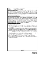
INSTALLATION OF THE MAJOR COMPONENTS:
CONTROL MODULE: (P/N 1365346)

Select a mounting location inside the passenger compartment (up behind the dash-
board). The mounting  location selected must be within 24" of the ignition switch wiring
harness to allow connection of the 6 pin main wiring harness.
Be certain that the chosen location will not interfere with proper operation of the vehicle.
Avoid mounting the module to or routing the wiring around the steering shaft/column, as
the module or wiring may wrap around or block the steering wheel preventing proper
control of the vehicle. Secure the module in the chosen location using cable ties or
screws as necessary.

Do Not Mount The Module In The Engine Compartment, as it is not waterproof.

THE RECEIVER/ANTENNA VALET SWITCH LED ASSEMBLY: (P/N 1181246)

The Superheterodyne Receiver Antenna Assembly which includes the LED and Valet/Pro-
gramming switch provided with this unit allows routing from below the dash board for maxi-
mum operating range. Choose a location above the belt line (dashboard) of the vehicle for
best reception. Special considerations must be made for windshield glass as some newer
vehicles utilize a metallic shielded window glass that will inhibit or restrict RF reception. In
these vehicles, route the antenna toward a rear window location for best reception. Secure
the antenna with double stick tape provided. After securing the antenna with tape, we
advise also securing a section of the antenna cable to a fixed support. This will prevent the
antenna from dropping down in case the double stick tape is exposed to extreme heat
which may loosen its gummed surface. Route the connector toward the control module
using caution not to pinch the cable as this will cause poor or no RF reception to the
control module. Connect the 5 pin cable to the mating connector of control module.

HOOD PIN SWITCH: (P/N 1363699)

The pin switch included in this package are intended for protecting the hood area of the
vehicle. In all cases, the switch must be mounted to a grounded metal surface. When the
pin switch is activated, (hood/trunk open),  it will supply a ground to the input wire to inhibit
the remote start function. In addition, the hood switch is required for the safety shut down
of the remote start unit. If the vehicle is being worked on, this hood switch prevents the
remote start activation even if the RF command to start is issued. 

This switch must be

installed in all applications. Failure to do so may result in personal injury or
property damage.

Mount the switch in the hood locations away from water drain paths. If necessary, a bracket
may be used to move the switch away from rain gutters or allow mounting to the firewall
behind the hood seal. In both cases the switch must be set up to allow the hood to depress
the switch at least 1/4 inch when the hood is closed and fully extended when the hood is
opened. For direct mounting, a 1/4 inch hole must be drilled. Carefully check behind the
chosen location to insure the drill will not penetrate any existing factory wiring or fluid lines.
Drill a 1/4" hole in the desired location and thread the pin switch into it using a 7/16" nut
driver or deep well socket. If using the mounting bracket, first secure the bracket to the
desired location and secure the pin switch in the pre-threaded mounting bracket hole.

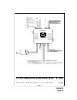
DO NOT PLUG THE SIX PIN MAIN POWER HARNESS OR THE MULTI PIN INPUT /
OUTPUT HARNESS INTO THE CONTROL MODULE UNTIL ALL CONNECTIONS TO THE
VEHICLE HAVE BEEN MADE. AFTER SELECTING YOUR TARGET WIRES AS DE-
FINED BELOW, DISCONNECT THE NEGATIVE BATTERY CABLE FROM THE VEHICLE
BATTERY PRIOR TO MAKING ANY CONNECTIONS.

Summary of Contents for PA-420C

Page 1: ...ble Duration Selectable RF Start Chirp Car Finder Mode Can elect to have horn beep along with parking lights if connected Selectable Run Times 5 10 15 or 20 Minutes Selectable Gas or Diesel Automatic...

Page 2: ...nch the cable as this will cause poor or no RF reception to the control module Connect the 5 pin cable to the mating connector of control module HOOD PIN SWITCH P N 1363699 The pin switch included in...

Page 3: ...l realize why the connection of the safety wire is required for all mechanical switch con figurations Failure to make this connection properly can result in personal injury and property damage In all...

Page 4: ...es today have factory door lock relays which can be connected directly to this output however always confirm that the factory relays in your particular vehicle do not exceed the rated 250mA output of...

Page 5: ...128 9239 5 of 24 Page 5...

Page 6: ...lsed ground output after the remote start unit shuts down and the G W R O P turns off This output will occur regardless of whether the circuit times out or is manually terminated Typically this output...

Page 7: ...e to do so may result in personal injury or property damage This wire may also be used if the vehicle brake light circuit switches ground to the brake lights An isolation diode must be used for ground...

Page 8: ...to the On position 2 Press and release the valet program push button switch 3 times 3 Immediately turn the ignition key Off 4 Press and hold the valet program push button switch then start the vehicl...

Page 9: ...ash Default 1 RF Start Chirp Off On On 2 Run Time 5 Min 10 Min 15Min 20 Min 10 Min 3 Park Lights On Steady Flash Steady 4 Input Check Voltage Tach DBI Tach Hybrid Tach 5 Voltage Level 0 5V B4 Start 0...

Page 10: ...with the individual component along with the proper 4 pin wiring harness requires to access the data transmit and receive as well as the proper voltage levels for the interface COMPLETING THE INSTALLA...

Page 11: ...128 9239 11 of 24 Page 11 2013 Audiovox Electronics Corporation Hauppauge NY 11788 128 9239 For technical support go to www prestigecarsecurity com or call 1 800 225 6074...

Page 12: ...ble Seleccionable RF Inicio Chirp Modo de buscador de coche puede elegir tener cuerno junto con las luces de estacionamiento si conecta una se al sonora Seleccionable Run Times 5 10 15 o 20 minutos Se...

Page 13: ...control con cautela para no pellizcar el cable ya que esto causar pobres o sin recepci n de RF al m dulo de control Conecte el cable de 5 pines en el conector del m dulo de control Interruptor de clav...

Page 14: ...y seleccionar el m todo de instalaci n correcta Adem s te dar s cuenta por qu es necesaria para todas las configuraciones del interruptor mec nico la conexi n del alambre de seguridad Si no se realiza...

Page 15: ...puerta de f brica desbloquear rel s que pueden conectarse directamente a esta salida sin embargo siempre confirmar que los rel s de f brica en su veh culo particular no excedan la capacidad de salida...

Page 16: ...rcuitos conmutados de bloqueo de puerta En esta aplicaci n se utilizar un rel para invertir la se al de salida de bloqueo de puerta del m dulo Conecte los alambre azul como se muestra a continuaci n C...

Page 17: ...de Banco 3 como puerta de desbloquear el pulso Alambre Azul Claro Pulsada salida negativa despu s de inicio El alambre de luz azul traza proporcionar un 1 segundo negativo de 250 mA pulsed salida desp...

Page 18: ...contacto de salida del rel de luz de estacionamiento Conecte este alambre al veh culo alambre de activaci n de luz de estacionamiento 5 Pin Entrada Salida de accesorio arn s conector P N 1124266 Alam...

Page 19: ...ativa 250mA que se convierte en activas 3 segundos antes de que el control remoto iniciar m dulo inicializa y sigue siendo negativo mientras que el m dulo est activo un es adicional de 2 segundos desp...

Page 20: ...isor que desea programar Consulte propietario guia para transmisor adicional de programaci n 3 Apague el interruptor de encendido a continuacion en Esto tiene acceso a Banco de funci n 2 alarma sin ll...

Page 21: ...po ADS DBI ADS 12 De tiempo Inicio cada 2 Horas cada 4 Horas Cada 4 horas automatico Diagn sticos Introduzca 3 Banco y Activar funci n seleccionable 7 como se describe en la secci n de selecci n y aju...

Page 22: ...de datos de 4 PIN Puerto de 4 pines ubicado al costado de este m dulo es paraAudiovox propietarios m dulos de interfaz del bus de datos Estos m dulos se utilizan para acceder a una variedad de caracte...

Page 23: ...ables hacia arriba y alejados de las piezas m viles y calientes que entre en contacto con debajo del tablero o en las reas del compartimento del motor PRECAUCI N Evite el rea cerca de la direcci n de...

Page 24: ...128 9239 24 of 24 Page 24 Para soporte t cnico vaya a www prestigecarsecurity com o llame al 1 800 225 6074 2013 Audiovox Electronics Corporation Hauppauge NY 11788 128 9239...

Reviews: