


BA_PH_245-100-300_EN_06-22.docx
44
14.2.4
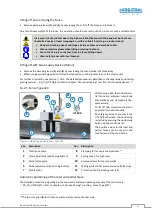
Fence Type 311
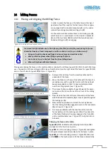
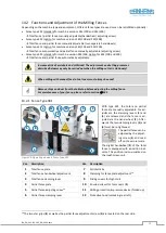
Figure 35: Operating elements Fence Type 311
With this type, the total fence is adjusta-
ble automatically and the partial fence
manually. The two clamping levers (
3
)
and (
6
) must first be loosened. Then the
total fence can be adjusted automatically
via the UT 300 control unit.
Once the fence has been reached the de-
sired position, the two clamping levers
must be re-tightened.
The partial fence can be
adjusted by the adjusting
screw (
5
) and read off on
the vernier scale.
The total fence is additionally visualised
on the touchscreen of the control unit.
Pos. Description
Pos. Description
1
Total fence plate
7
Splinter tabs
2
Total fence handwheel adjustment
8
Clamping for fence plate adjustment
13
3
Total fence clamping lever
9
Sliding covers for high tools
4
Partial fence plate
10
Knurled screws for tool covers (
9
)
5
Partial fence adjusting screw
11
Milling protection & pressure device (folded up)
6
Partial fence clamping lever
12
Protective hood (unlocking rear left)
Automatic positioning of the total fence
The detailed procedure is described in the separately enclosed operating manual of the control unit
BA_PH_UT300_EN
(refer to chapter „
Fence positioning
“ / section „
Fence Type 311
“).
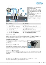
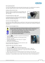
Folding up the protective hood
Before the protective hood (
12
) of the fence can be folded up, the
locking bolt (
V
) at the rear left must be unlocked by pulling it out
(see
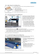
Fit a grooved board or safety rulers
To insert a grooved board or safety rulers, remove the splinter tabs
(
7
), attach the grooved board or safety rulers as fence bridges and
fasten them via the free threaded holes.
Figure 36: Locking bolt of Type 311
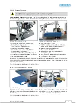
Tool covers for high milling arbors
By opening the knurled screws (
10
), the two cover plates can be moved, which is particularly advantageous with
high milling arbours. The opening should always be closed as far as possible without touching the milling arbor
or the cutter.
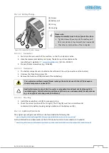
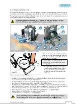
Fence plate adjustment
Loosen the star grip (
8
) and push the fence plate (
1
) to the desired position. Then retighten the star grip (
8
).
Always adjust the plates so that they cover as much of the tool as possible without touching it.
13
The two star grips (
8
) as well as the partial fence adjustment screw (
5
) are located on the rear side.
6
1
4
7
10
9
5
8
11
3
2
UT 300
12
V