SMARTZONE G5 USER MANUAL
6
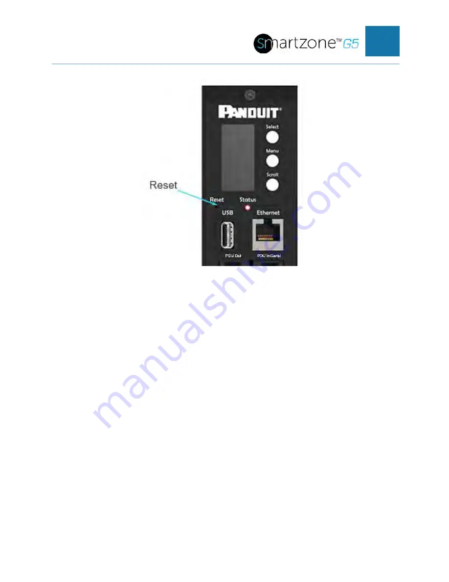
Locate the Reset button (figure 2)
Setup Serial Communication
You may configure the network settings using the command line interface (CLI) with a
serial connection. Users can connect serially using the optional RJ45-DB9 cable (or
make your own cable by creating a unique pinout as described below in the “Serial
Cable Pinout to Create Your Own Cable” in Section 4).
1. Verify that the computer has a serial port. If your computer does not have a DB9
serial connector, but does have a USB connector, obtain a USB-to-DB9 Adapter to
convert the USB to a DB9 serial port.
2. Using the optional RJ45-DB9 cable, connect the RJ-45 end to the port labeled
“RS485-1” on the front panel of your PDU model (see Figure 2). Connect the
DB9 end of the cable to the computer.
3. Open the terminal emulation program (HyperTerminal or PuTTY) on the computer
and select the serial port connection (such as COM1).
4. Set the communications port as follows:
•
Bits per second: 115200
•
Data bits: 8
Summary of Contents for smartzone G5
Page 1: ...G5 PDU User Manual...
Page 11: ...SMARTZONE G5 USER MANUAL 10 Login Page Introduction to Web GUI...
Page 14: ...SMARTZONE G5 USER MANUAL 13 Environmental Page Security Page...
Page 35: ...SMARTZONE G5 USER MANUAL 34 Connect the RJ 45 end of the cable to the Serial RS485 1 connector...
Page 45: ...SMARTZONE G5 USER MANUAL 44...
Page 50: ...SMARTZONE G5 USER MANUAL 49 FOR 1 PHASE WITH BREAKERS FOR 3 PHASE WITH 6 BREAKERS...
Page 53: ...SMARTZONE G5 USER MANUAL 52 2 Select Outlet Control Enabled...
Page 55: ...SMARTZONE G5 USER MANUAL 54 5 Your Outlet Power Sequence has been set...
Page 59: ...SMARTZONE G5 USER MANUAL 58 9 RNA is now configured and enabled...


