INSTALLATION INSTRUCTIONS PN355
For Technical Support: www.panduit.com/resources/install_maintain.asp
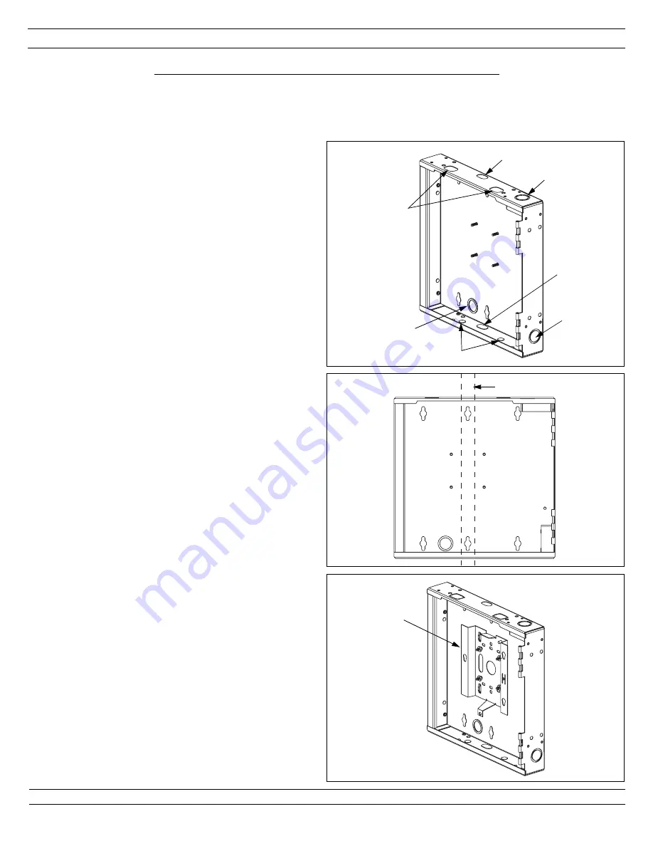
Step 1: Knockout Removal
1
D
A
F
E
G
B
C
2.1 Locate the wall studs.
2.2 Hold the enclosure against the wall to mark the
location of the mounting holes.
2.3 Mount the enclosure to the wall using mounting screws
and wall anchors (not included). Enclosure designed
for use with #14 screws.
Step 2: Mount Enclosure to Wall
Page 2 of 8
EXTERNAL WALL MOUNT INSTALLATION
3.1 Place the Wireless Access Point Mounting Bracket
(supplied with the Cisco Aironet 1200 Wireless Access
Point) inside the enclosure so the four angled mounting
slots align with the four threaded studs on the back
wall of the enclosure. Install the bracket in the
orientation as shown in the view.
3.2 Secure the mounting bracket with the supplied #8 Split
Lock Washers and #8-32 Hex Nuts.
Step 3: Install Wireless Access Point Bracket
3
Mounting
Bracket
Refer to the installation and configuration guidelines provided by the manufacturer of the wireless
access point to determine the optimum enclosure installation location and antenna configuration.
Please read these instructions in their entirety prior to installing the enclosure.
2
2 x 4 Stud
1.1 Determine whether the network cable will be routed into
the enclosure through conduit or surface raceway.
Remove the appropriate knockouts.
For Conduit
- Remove knockout “A”, “B” or “C”. This
double knockout accommodates either 1/2" or 3/4"
conduit.
For Surface Raceway - Remove knockout “D” or “E”.
This opening accommodates
PANDUIT
LD10 surface
raceway.
1.2 Determine the antenna type that will be used. Remove
the appropriate knockouts.
If 2.4GHz Standard Dipole Antennas will be used with
the Wireless Access Point (WAP) - Remove knockouts
“F”.
For Externally Mounted Antennas - Remove knockouts
“G”. An antenna patch cord (not included) is required
for this application.
1.3 Locate the wall studs. Position the enclosure on the wall
and identify which keyed knockouts should be removed.
It is recommended that two of the mounting holes be
aligned with the wall stud. Wall anchors (not included)
should be used for each additional mounting hole
chosen by the installer. Remove desired knockouts.
1.4 To view the LED lights on the WAP when the enclosure
door is closed, remove knockout “J”. Refer to figure 1
on page 5 for location of knockout “J”.
Optional:
Flexible grommet edging can be used to cover
knockout edges if desired.


