Networked POU
Version 1.0
3
Contents
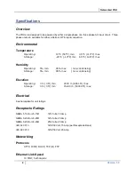
SPECIFICATIONS ..........................................................................................................................4
Overview ....................................................................................................................................4
Environmental ............................................................................................................................4
Temperature .........................................................................................................................4
Humidity ................................................................................................................................4
Elevation ...............................................................................................................................4
Electrical.....................................................................................................................................4
Receptacle Ratings ....................................................................................................................4
Networking .................................................................................................................................4
Protocols ...............................................................................................................................4
Ethernet Link Speed .............................................................................................................4
Data Formats .............................................................................................................................5
EMC Verification ........................................................................................................................5
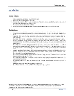
INSTALLATION ..............................................................................................................................6
Instructions .................................................................................................................................6
Guidelines ..................................................................................................................................6
MOUNTING .....................................................................................................................................7
"L" Bracket .................................................................................................................................7
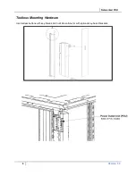
Toolless Mounting Hardware .....................................................................................................8
NETWORKED MONITORING ..................................................................................................... 10
PViQ Local Meter Overview .................................................................................................... 10
PViQ Networked Monitoring Instructions ................................................................................ 10
Setting an IP Address ........................................................................................................ 10
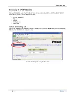
Accessing the POU Web GUI ................................................................................................. 12
Current Monitoring tab ....................................................................................................... 12
Display tab ......................................................................................................................... 13
Alarms tab .......................................................................................................................... 14
Configuration tab ............................................................................................................... 15
LED Display ....................................................................................................................... 16
Viewing the IP Address/Resetting to Default IP ................................................................ 16
Rebooting the Meter ............................................................................................................... 17
Web Page .......................................................................................................................... 17
SNMP/XML ........................................................................................................................ 17
Sample Usage ................................................................................................................... 18
SERVICE AND TECHNICAL SUPPORT .................................................................................... 19
Service .................................................................................................................................... 19
Technical Support ................................................................................................................... 19


