

IN-SERVICE TOOLS - AFTER TOOLS HAVE BEEN IN SERVICE:
NEW TOOLS - BEFORE PLACING INTO SERVICE:
INSPECTION /MAINTENANCE
1. Twist the ends of the stripped wire together,
trim and set aside. Refer to product
packaging for wire strip length.
2. With the handles in the
open
position, swing
the locator out of the way (See Figure 4). The
locator will detent and “lock” in this position.
Insert the wire joint from the back (locator)
side of the crimp tool in the proper crimp
pocket (See Figure 1) so that the ribs of the
molded insulator (where applicable) are
positioned against the crimp die (See Figure
9). Refer to product packaging for selection of
proper crimp pocket.
3. Close the handles until the barrel is held
snugly in position—do not deform the barrel.
4. Insert the prepared wires into the wire joint.
Crimp the wire joint by closing the handles
until the controlled cycle mechanism releases.
Upon release, the handles will open
automatically and the crimped joint can be
removed.
INSULATED WIRE JOINT CRIMPING
INSTRUCTIONS
VISUAL INSPECTION
1. Visually inspect the tool for missing or loose
pins, then close the tool and note the return
action of the handles.
2. Swing the locator out of the way (See Figure
4), and inspect the crimping dies for worn,
chipped or broken edges.
3. If parts are missing, defective or damaged,
contact Panduit Customer Service for
information on repair or replacement of tools.
TROUBLESHOOTING
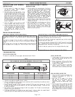
DIE CLOSURE INSPECTION
PRELOAD FORCE INSPECTION
Die closure is measured by using pin gages (dimensions listed in Table 1).
1. Clean the crimping dies and gage member surfaces.
2. Close the tool handles until the crimping dies are bottomed and the controlled cycle mechanism releas-
es. Keep the handles closed together.
3. Using the appropriate gage member, attempt to insert the NO GO gage into the die opening. The NO
GO side may partially enter the die closure but must NOT pass completely through. Perform this test
for both crimp pockets.
4. Repeat Step 3 with the appropriate GO gage for both crimp pockets. The GO side must enter and pass
completely through the die closures.
5. If both gage conditions are met, the tool is dimensionally correct. If either condition fails, contact Panduit
Customer Service, or Panduit EMEA Service Center for technical assistance.
1. Close the handles until the controlled cycle
mechanism is engaged but before the
mechanism releases.
2. Apply force to the handles 1-1/4" (32mm)
from the end of the handles, until the
controlled cycle release mechanism
releases. Record the reading using a force
gauge.
3. The force required to release the controlled
cycle release mechanism should be a
minimum
of 15 pounds-force (67 N). If the
force required is less than 15 pounds-force
(67 N), contact Panduit Customer Service, or
Panduit EMEA Service Center for technical
assistance.
Table 1
Figure 8
Figure 9
All Panduit crimping tools are calibrated and inspected before they are
shipped from the factory. All new tools should be inspected before being
used.
New tools are shipped, factory lubricated, in protective packaging. After
inspection, simply clean any excess oil from the crimping dies and place into
service.
When the tool is not in use, keep the handles closed to prevent objects from
becoming lodged in the crimping area. Store the tool in a clean, dry area.
It is recommended that each operator of the tool be made aware of - and
responsible for following these maintenance steps.:
In-service tools should be cleaned and inspected at least ONCE A MONTH.
To clean-wipe with a clean cloth.
In-service tools should be lubricated ONCE A WEEK, and after every clean-
ing. Lubricate all pins, pivots and bearing surfaces with DOW CORNING
®
Molykote BR2 Plus. Do not use oil excessively.
Be sure to clean any excess oil from the crimping dies before using.
® Molykote BR2 Plus is the Registered Trademark of DOW CORNING
DIE CLOSURE GO / NO GO GAGE MEMBERS - TOOL NO. CT-1550
CRIMP POCKET
“G” Dia. (GO)
“NG” Dia. (NO GO)
22 - 14
0.101
0.109
12 - 10
0.147
0.155
1. With the handles in the
closed
position, (See Figure
1), rotate the locator until the wide slot is centered
between the crimp pockets (See Figure 7). The
locator will detent and “lock” in this position.
Squeeze the handles to open the tool. With the back
of the disconnect tongue turned toward the color
dots, insert the disconnect in the proper crimp
pocket (See FIgure 1) so that the tongue slides into
the locator slot (See Figure 8). Refer to product
packaging for selection of proper crimp pocket.
2. Hold the disconnect against the locator and close the
handles until the barrel is held snugly in place—do
not deform the barrel.
3. Insert the stripped wire into the disconnect. Refer to
product packaging for wire strip length. Crimp the
disconnect by closing the handles until the controlled
cycle mechanism releases. Upon release, the
handles will open automatically and the crimped
disconnect can be removed.
INSULATED DISCONNECT CRIMPING
INSTRUCTIONS
Page: 2 of 2
© Panduit Corp. 2017
OPERATION INSTRUCTIONS
CT-1550


