Panduit Atlona Omega AT-OME-EX-TX Installation Manual Download Page 10

10

Installation Guide

AT-OME-EX-TX

Requirements:

• 

AT-OME-EX-TX

• 

Firmware file

• 

Computer running Windows

• 

USB-A to USB mini-B cable

1.  Disconnect power from the unit.
2.  Connect a USB-A to USB mini-B cable between the PC and the 

FW

 port on the unit.

3.  Power the unit.  Make sure the receiver is powered and a category cable is connected 

between the HDBaseT ports of both the transmitter and receiver units.

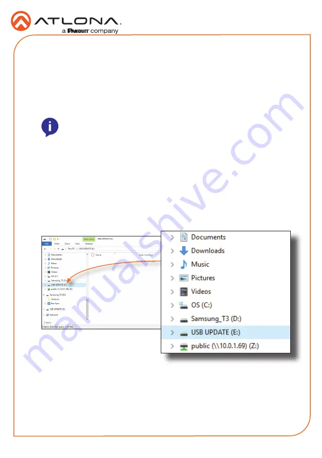
4.  The USB UPDATE folder will be displayed.  If this folder is not displayed, automatically, 

select the USB UPDATE drive from Windows Explorer.

5. 

Delete all files from the USB UPDATE drive, if any are present.

NOTE:

 The update process can take up to five minutes to complete.

6. 

Drag-and-drop the firmware file to the drive.

7.  The 

PWR

 LED indicator, on the front panel, will flash green while the unit is being updated.  

Do not disconnect the USB cable during the update process.  When the 

PWR

 LED stops 

flashing and is solid green, the update process will be complete.

8.  Disconnect the USB cable from the unit and repeat for any additional units.

Updating the Firmware

Summary of Contents for Atlona Omega AT-OME-EX-TX

Page 1: ...on is ideal for software video conferencing and the use of touch or interactive displays The OME EX TX includes a USB host for a PC plus two peripheral devices such as a speakerphone microphone or key...

Page 2: ...r will glow green when the AT OME EX TX is powered The AT OME EX RX supplies power to the AT OME EX TX over HDBaseT The LINK LED indicator glows yellow when a solid link is established between the tra...

Page 3: ...al using one of the included 4 pin captive screw connectors 4 Repeat step 2 for the S and GND wires for the IR connection 5 Insert the S signal wire in to the TX terminal and the ground wire to the GN...

Page 4: ...rol system and the RS 232 port on the transmitter Refer to RS 232 and IR page 3 for more information 7 OPTIONAL Connect an IR emitter to the IR port Refer to RS 232 and IR page 3 for more information...

Page 5: ...r patch cables are not recommended Off The link integrity between the transmitter and the receiver is compromised Check the category cable between the HDBaseT IN port on the transmitter and the HDBase...

Page 6: ...ing brackets 1 Using a small Phillips screwdriver remove the two screws from the left side of the enclosure 2 Position one of the mounting brackets as shown below aligning the holes on the side of the...

Page 7: ...to attach the second mounting bracket to the opposite side of the unit 5 Mount the unit to a flat surface using the oval shaped holes on each mounting bracket If using a drywall surface a 6 drywall sc...

Page 8: ...B A cable from the FW port on the transmitter to a computer 5 Click the Port drop down list and select the COM port then click the Connect button The Analyzer software provides HDBaseT testing debuggi...

Page 9: ...and an active display to the receiver Set the source to the highest resolution 4 Connect a mini USB to USB A cable from the FW port on the transmitter to a computer 5 Click the Port drop down list an...

Page 10: ...l be displayed If this folder is not displayed automatically select the USB UPDATE drive from Windows Explorer 5 Delete all files from the USB UPDATE drive if any are present NOTE The update process c...

Page 11: ...11 Installation Guide AT OME EX TX Notes...

Page 12: ...na Inc All other brand names and trademarks or registered trademarks are the property of their respective owners Pricing specifications and availability subject to change without notice Actual product...

Reviews: