Panduit ATLONA AT-HDR-CAT-4 Installation Manual Download Page 6

6

Installation Guide

AT-HDR-CAT-4

DC 48V

IR

RS-232

RX TX

RX

TX

HDMI

IN

OUT

1

2

3

HDBaseT OUT

LAN

4

IR

RX TX

RX

TX

RS-232

1

IR

RX TX

RX

TX

RS-232

2

IR

RX TX

RX

TX

RS-232

3

IR

RX TX

RX

TX

RS-232

4

AUDIO OUT

R

L

AT-HDR-CAT-4

OUT

IN

HDMI

4

3

2

1

HDBaseT

LOCK

INT LEARN

FW

EDID

POWER

The AT-HDR-CAT-4 is shipped with DHCP enabled.  Once connected to a network, the DHCP 

server (if available), will automatically assign an IP address to the unit.  If the AT-HDR-CAT-4 

is unable to detect a DHCP server within 15 seconds, then the unit will use a self-assigned IP 

address within the range of 

169.254.xxx.xxx/16

.  If this occurs, refer to the AT-HDR-CAT-4 

User Manual for more information.

Use an IP scanner, along with the MAC address on the bottom of the unit, to identify the unit on 

the network.  If a static IP address is desired, the unit can be switched to static IP mode.

IP Configuration

Switching the IP mode using the Front Panel

1.  Make sure the AT-HDR-CAT-4 is powered.
2.  Connect an Ethernet cable between the LAN port of the AT-HDR-CAT-4 and the Local Area 

Network (LAN).

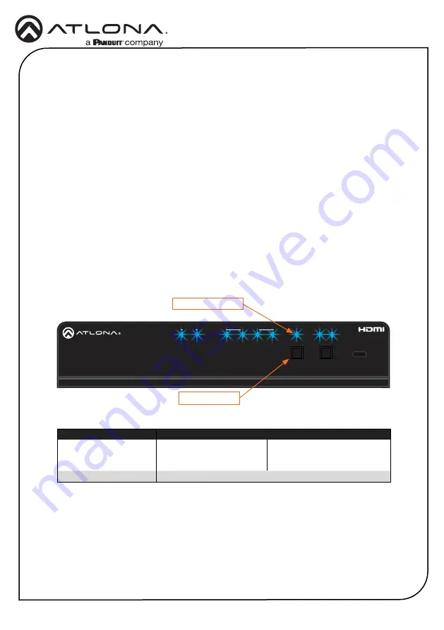
3.  Press and hold the POWER button for approximately 15 seconds.  Release the POWER 

button once all the front-panel LED indicators begin to flash.  The number of flashes will 

indicate the currently selected IP mode.  Refer to the table, below.


POWER button flashes

Description

Two

Static IP mode

IP address: 

192.168.1.254

Netmask:    

255.255.0.0

Gateway:    

192.168.1.1

Four

DHCP mode

LOCK LED indicator

POWER button

Switching the IP mode can also be performed using commands or the built-in web server.  

Refer the AT-HDR-CAT-4 User Manual for more information.

Summary of Contents for ATLONA AT-HDR-CAT-4

Page 1: ...ons including HDMI pass through audio de embedding EDID management CEC display control RS 232 and IR control extension remote power for receivers and HDBaseT link testing It offers compatibility with...

Page 2: ...eT receiver with an active sink the LED indicator will be blue If no active sink is connected or the sink is powered off then the indicator will not be illuminated 3 Lock This LED will be blue when th...

Page 3: ...OUT Connect an HDMI cable from this port to an HDMI input on a local display or an additional AT HDR CAT 4 unit 5 RS 232 IR 1 4 Connect a control system or other DTE device to these ports for pass th...

Page 4: ...insert the copper wiring 2 Wire the included power supply to the block as shown below Do not use high torque devices when securing the wires to the captive screw terminal block as this may damage the...

Page 5: ...Meters HDMI 15 5 30 10 CAT5e 6 115 35 200 60 CAT6a 7 130 40 230 70 4 Connect an Ethernet cable from the LAN port to the Local Area Network LAN This step will be required in order to access the built i...

Page 6: ...the MAC address on the bottom of the unit to identify the unit on the network If a static IP address is desired the unit can be switched to static IP mode IP Configuration Switching the IP mode using...

Page 7: ...is connected between the LAN port on the AT HDR CAT 4 and the network 2 Launch a web browser and enter the IP address of the unit 3 The AT HDR CAT 4 Register page will be displayed 4 Create a usernam...

Page 8: ...re the property of their respective owners Pricing specifications and availability subject to change without notice Actual products product images and online product images may vary from images shown...

Reviews: