


OMAP
TM
4 PandaBoard System
Reference Manual
Revision 0.4
September 22, 2010
DOC-21010
Page 30 of 83
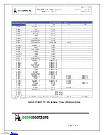
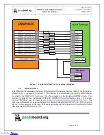
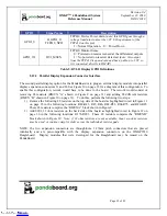
GPIO
Dir
Signal Name
Description
GPIO_41 O
HDMI_LS_OE
TPD12S015 Level Shifter and internal LDO Enable
1 = Enabled, 0 = Disabled
GPIO_60 O HDMI_CT_CP_HPD
TPD12S015 DC/DC Converter and Hot-Plug Detect
Enable 1 = Enabled, 0 = Disabled
Table 4: HDMI GPIO Definitions
2.12
Display Interface
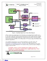
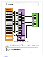
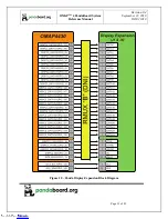
The PandaBoard provides two possible options for the usage of the OMAP4430 parallel display signals.
The first option (the as-shipped default configuration) routes them to a TFP410 DVI transmitter, whose
output feeds an onboard DVI-D connector. The second option routes them to a pair of 20-pin LCD
expansion connectors (J1 and J4). Both of these possible options are discussed in the following
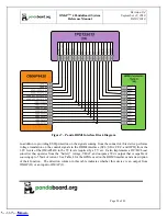
paragraphs. See Figure 8 for a diagram of the PandaBoard Display Interface. The path shown in red in
Figure 8 is the as-shipped default configuration.
(J1 & J4)
(U2)
(P1)
Figure 8 – Panda Display Interface Block Diagram
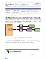
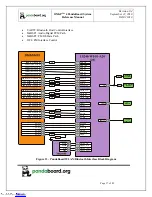
2.12.1
Parallel Display DVI-D connector
As mentioned previously, the as-shipped parallel display interface configuration for the PandaBoard is
with the parallel display interface signals from OMAP driven to a TFP410 DVI transmitter, whose output
feeds an onboard DVI-D connector. See Figure 9 for a block diagram of this interface.
Downloaded from
Downloaded from
Downloaded from
Downloaded from
Downloaded from
Downloaded from
Downloaded from
Downloaded from
Downloaded from
Downloaded from
Downloaded from
Downloaded from
Downloaded from
Downloaded from
Downloaded from
Downloaded from
Downloaded from
Downloaded from
Downloaded from
Downloaded from
Downloaded from
Downloaded from
Downloaded from
Downloaded from
Downloaded from
Downloaded from
Downloaded from
Downloaded from
Downloaded from
Downloaded from


