background image

31

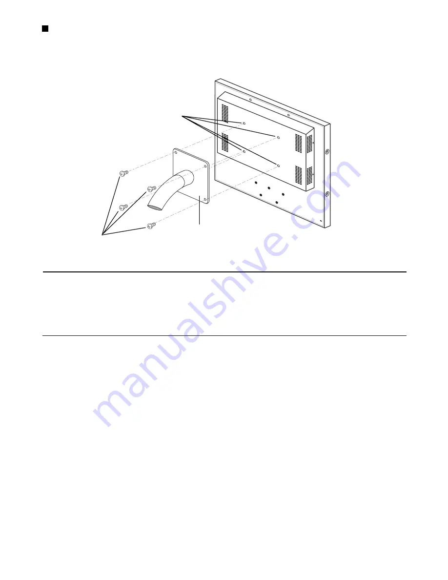
Vis de montage au mur (dispo-
nibles dans le commerce)

Orifices de montage VESA 
(écart de 100 mm)

Support à écart de vis de 100 mm conforme aux 
normes VESA (disponibles dans le commerce)

Montage au mur

Pour installer ce moniteur au mur, utiliser un support à écart de 100 mm répondant aux normes VESA (disponible dans le commerce) ainsi 
que quatre vis (disponibles dans le commerce).

Mises en garde :

•  Ne jamais obstruer les orifices d’aération du couvercle afin d’éviter une surchauffe de l’appareil.
•  Si le moniteur doit être installé dans un endroit soumis à de fortes vibrations, veiller à bien bloquer l’arrière du moniteur à l’aide d’un 

renfort en angle.

•  Afin de maintenir la température à l’intérieur du bâti et le long du mur inférieure à 40 °C, laisser assez d’espace libre (plus d’1 U) ou 

installer un ventilateur.

•  L’adaptateur CA ne devrait pas être placé à l’intérieur du bâti ou contre le mur, afin de ne pas contribuer inutilement à l’augmentation 

de la température.

Summary of Contents for WVLC1710 - LCD MONITOR

Page 1: ...Video Monitor Operating Instructions Model No WV LC1710 Before attempting to connect or operate this product please read these instructions carefully and save this manual for future use ENGLISH FRANÇAIS ...

Page 2: ...arthed To reduce the risk of fire or electric shock do not expose this appliance to rain or moisture The apparatus shall not be exposed to dripping or splashing and that no objects filled with liquids such as vases shall be placed on the apparatus Caution Before attempting to connect or operate this product please read the label on the rear This Class A digital apparatus complies with Canadian ICE...

Page 3: ...r outlet consult an electrician for replacement of the obsolete outlet 10 Protect the power cord from being walked on or pinched particularly at plugs convenience receptacles and the point where they exit from the apparatus 11 Only use attachments accessories specified by the manufacturer 12 Use only with the cart stand tripod bracket or table specified by the manufacturer or sold with the apparat...

Page 4: ... S DISCLAIMER OF WARRANTY 2 PERSONAL INJURY OR ANY DAMAGE CAUSED BY INAPPROPRIATE USE OR NEGLIGENT OPERATION OF THE USER 3 UNAUTHORIZED DISASSEMBLE REPAIR OR MODIFI CATION OF THE PRODUCT BY THE USER 4 ANY PROBLEM CONSEQUENTIAL INCONVENIENCE OR LOSS OR DAMAGE ARISING OUT OF THE SYSTEM COMBINED BY THE DEVICES OF THIRD PARTY IN NO EVENT SHALL MATSUSHITA ELECTRIC INDUSTRI AL CO LTD BE LIABLE TO ANY PA...

Page 5: ... 10 CONNECTIONS 11 Connection with the Camera Site 12 Multiple Monitor Connection 12 Connection with the Digital Disk Recorder 12 Connection with PC 12 Connection with DVD 12 STARTUP 13 AUDIO VOLUME CONTROL 14 DISPLAYING VIDEO ADJUSTMENT MENU 15 Displaying Video Adjustment Menu 15 Setting of Composite Video S Video Component Video Input 16 Setting of PC Input 18 Picture in Picture Mode Monitoring ...

Page 6: ...midity below 90 The input power source for this appliance is 100 V AC to 240 V AC 50 60 Hz with AC Adapter Do not use strong or abrasive detergents when cleaning the appliance body Use a dry cloth to clean the appliance when it is dirty When the dirt is hard to remove use a mild detergent and wipe gently Afterwards wipe the remained part of the detergent in it with a dry cloth The surface of the d...

Page 7: ...These buttons move the cursor to the item parameters in the Video Adjustment Menu PIP Down POS Up PIP Button Picture In Picture Pressing this button displays or removes display of sub screen When Video S Video or Component input is currently on main screen PC input displays on subscreen When PC input is currently on main screen Video S Video or Component input displays on subscreen POS Button Posi...

Page 8: ...rity slot This slot can be used to insert lock based on Industry Standard Specification 3 3 26 mm 7 7 26 mm 2 5 4 mm for theft prevention OUT OF RANGE This monitor supports the timing data listed below It also supports in part other timing data not listed on the table VESA Video Electronics Standards Association Notes OUT OF RANGE is displayed on the center of the screen when the input resolution ...

Page 9: ...crews M4 12 INSTALLATION 1 Remove two M4 screws to remove the stand cover 2 Remove the stand assembly by removing four M4 screws from the stand 3 Remove the stand arm by removing the three remaining M4 screws 1 Remove four screws on both side panels 2 Mount the rack mount brackets to the sides of the moni tor Fix the rack mount brackets by using four supplied screws M4 12 3 Mount the upper rack mo...

Page 10: ...rews procured locally Cautions Do not block the ventilation opening or slots on the cover to prevent from overheating When installing on places with vibration fix securely the rear of the monitor by using reinforcement angle To keep the temperature in the rack or wall where this monitor is installed within 40 C 104 F leave enough space more than 1 U or install a cooling fan AC Adapter should not b...

Page 11: ...TIONS Digital Disk Recorder Video Output S Video Output Audio Output Video Output PC AC Adapter Supplied Accessory Power Cord Supplied Accessory Y Cb Cr Component Output DVD Video Input Audio Input Video Monitor ...

Page 12: ...Disk Recorder for this monitor Connect the PC IN connector of this monitor to the video output analog RGB of the PC or other equipment using VGA cable Connection with PC Connect the COMPONENT IN connectors of this monitor to the component output connectors of DVD of other video equipment using coaxial cables Connection with DVD Cable Recommended Cable Length RG 59 U 3C 2V RG 6 U 5C 2V RG 11 U 7C 2...

Page 13: ... normal video display Note During onscreen display of PROCESSING all buttons except POWER button are disabled All buttons are enabled after onscreen display of PROCESSING has disappeared When picture is set to PC input pressing the AUTO button initiates auto tuning of picture size and position Onscreen display of AUTO TUNING displays on the center of the screen as shown below NO SIGNAL AUTO TUNING...

Page 14: ...the or button when picture is displayed When these buttons are pressed the icon and digital display of audio volume setting appear on the upper left side of the screen Decreases the audio volume Increases the audio volume AUDIO VOLUME CONTROL ...

Page 15: ... NTSC signal is inputted PAL When PAL signal is inputted B W When black and white signal with 60 Hz 50 Hz field fre quency is inputted in composite video input During PC IN the current signal being displayed is in the form Horizontal Resolution Vertical Resolution Field Frequency on the latter part of the menu title based on the timing data list on page 8 Note In case the frequency of connected PC...

Page 16: ...erature 6500K Pictures are displayed in reddish color temperature 4 Move the cursor to the SCAN parameter with the PIP or POS button then select scanning area with or button FULL Vertical and horizontal picture size are equal to the display panel size Picture aspect ratio is dis regarded and the vertical size of picture is a little stretched OVER The vertical size of picture is fitted to the heigh...

Page 17: ...CAN FULL LANGUAGE ENGLISH NORMAL SETTINGS VIDEO IN Caution If power is cut off while setting it will not store the set tings that have changed 6 To reset the monitor to the default settings move the cursor to the NORMAL SETTINGS with the PIP or POS button then press the or button to restore the default settings Onscreen display of NORMAL SETTINGS as shown below appears on the center of the screen ...

Page 18: ...he cursor to either USER COLOR R USER COLOR G or USER COLOR B parameter in the menu with the PIP or POS button then adjust the red green or blue color for color temperature Decreases the red green or blue color Increases the red green or blue color 6 To reset the monitor to the default settings move the cursor to the NORMAL SETTINGS with the PIP or POS button then press the or button to restore th...

Page 19: ...is case adjust H POSITION and CLOCK following the procedure indicated in upper left note Picture in Picture Mode Monitoring The input signal of subscreen displays on the upper right of display panel 2 After displaying the subscreen pressing the POS button will move the subscreen as shown below 7 After setting the parameters press the MENU button Set values will be stored and the Video Adjustment M...

Page 20: ...u is not displayed when there is no input signal Press the INPUT SELECT button to change the input signal Volume cannot adjust even if the or button is pressed Volume cannot be adjusted when picture is not displayed Press the INPUT SELECT button to change to channel with input Input signal cannot change even if the INPUT SELECT button is pressed Position of picture display during PC input is shift...

Page 21: ...n Y 1 0 V P P 75Ω C 0 3 V P P 75Ω Mini DIN jack Component In Y 1 0 V P P 75Ω BNC connector Cb Cr 0 7 V P P 75Ω BNC connector 2 PC In R G B 0 7 V P P 75Ω H V sync TTL 15 pin Mini D sub Speaker Out 0 5 W Audio In 8 dB Hi Z RCA pin jack Audio Out Looped through output RCA pin jack Color Temperature Video In Standard 9300K 6500K PC In User color 9300K 6500K Sub picture Size 1 9 of full size picture Am...

Page 22: ...t Current 4 A Dimension 120 mm L 60 mm W 35 mm H without DC cable 4 18 25 L 2 9 25 W 1 9 25 H Weight 0 35 k 0 77 lbs STANDARD ACCESSORIES Operating Instructions this book 1 pc Warranty Certificate 1 pc The following items are for installation AC Adapter 1 pc Power Cord 1 pc AC Adapter g ...

Page 23: ...faut savoir que l appareil n est alimenté que dans la mesure où l interrupteur d alimentation à positions marche arrêt se trouve en position marche ON Débranchez le cordon d alimentation pour couper l alimentation générale de tous les appareils VERSION FRANÇAISE FRANÇAIS CAUTION RISK OF ELECTRIC SHOCK DO NOT OPEN ATTENTION AFIN DE PRÉVENIR LE RISQUE DE CHOCS ÉLECTRIQUES NE PAS RETIRER LES VIS TOUT...

Page 24: ...correctement dans votre prise prière de consulter un électricien pour qu il effectue le remplacement de l ancienne prise de sortie secteur 10 Voir à ce qu on ne marche pas sur le cordon d alimentation ou qu on ne l écrase pas particulièrement à l emplacement des fiches des prises de courant et de sa sortie de l appareil 11 Utiliser uniquement les fixations ou les accessoires spécifiés par le fabri...

Page 25: ...ESSURE CORPORELLE OU TOUT DÉGÂT CAUSÉ PAR UN USAGE INAPPROPRIÉ OU UNE UTILISATION NÉGLIGENTE DE L UTILISATEUR 3 LE DÉMONTAGE LA RÉPARATION OU LA MODIFICA TION NON AUTORISÉS DU PRODUIT EFFECTUÉS PAR L UTILISATEUR 4 TOUT PROBLÈME INCOMMODITÉ IMPORTANTE OU PERTE OU ENDOMMAGEMENT DÉCOULANT DE LA COMBINAISON DU SYSTÈME AVEC DES APPAREILS DE TIERS SAUF EN CE QUI TOUCHE AU REMPLACEMENT OU À L ENTRETIEN R...

Page 26: ... à un site de caméras 33 Raccord à plusieurs moniteurs 33 Raccord à un enregistreur de disques numériques 33 Raccord à un PC 33 Raccord à un DVD 33 DÉMARRAGE 34 COMMANDE DE VOLUME AUDIO 35 AFFICHAGE DU MENU DE RÉGLAGE VIDÉO 36 Affichage du menu de réglage vidéo 36 Configuration de l entrée vidéo composite S vidéo vidéo en composantes 37 Configuration de l entrée PC 39 Visionnement en mode Image da...

Page 27: ...lant de 0 C 40 C et avec une humidité inférieure à 90 La gamme des tensions applicables à cette unité va de 100 V CA à 240 V CA 50 60 Hz avec un adaptateur CA Ne jamais utiliser des détergents forts ou abrasifs pour nettoyer le boîtier de l appareil Quand l appareil est sale le nettoyer avec un linge sec Si la saleté est tenace utiliser un détergent doux en frottant lentement Essuyer ensuite les r...

Page 28: ...uilles d une montre la position de l image incrustée dans un des quatre coins de l écran ACL g Touches de diminution augmentation AUDIO Appuyer sur ces touches pour augmenter ou réduire le volume sonore Ces touches permettent également de sélectionner certains paramètres ou niveaux dans le menu de réglage vidéo h Panneau d affichage i Enceinte j Support du moniteur k Connecteur d entrée audio AUDI...

Page 29: ...utilise pour y placer un verrou en conformité avec les caractéristiques définies par les normes industrielles 3 3 26 mm 7 7 26 mm 2 5 4 mm pour empêcher les vols OUT OF RANGE Ce moniteur prend en charge les données de synchronisation ci dessous Il peut néanmoins prendre en charge d autres données de syn chronisation non répertoriées dans cette liste VESA Video Electronics Standards Association Ass...

Page 30: ...ntage M4 12 INSTALLATION 1 Dévisser les deux vis M4 pour pouvoir retirer le couver cle du support 2 Retirer l ensemble du support en dévissant les quatre vis M4 du support 3 Retirer le bras du support en dévissant les trois vis M4 restantes 1 Dévisser les quatre vis des deux côtés du panneau 2 Installer les deux supports de chaque côté du moniteur Fixer les supports de montage sur bâti à l aide de...

Page 31: ...es en garde Ne jamais obstruer les orifices d aération du couvercle afin d éviter une surchauffe de l appareil Si le moniteur doit être installé dans un endroit soumis à de fortes vibrations veiller à bien bloquer l arrière du moniteur à l aide d un renfort en angle Afin de maintenir la température à l intérieur du bâti et le long du mur inférieure à 40 C laisser assez d espace libre plus d 1 U ou...

Page 32: ... de disques numériques Sortie vidéo Sortie S vidéo Sortie audio Sortie vidéo PC Adaptateur CA accessoire fourni Cordon d alimentation accessoire fourni Y Cb Cr Sortie en composantes DVD Entrée vidéo Entrée audio Moniteur vidéo ...

Page 33: ...umériques avec ce moniteur Brancher le connecteur PC IN de ce moniteur sur la sortie vidéo RGB analogique du PC ou d un autre appareil similaire à l aide d un câble VGA Raccord à un PC Brancher les connecteurs COMPONENT IN de ce moniteur aux connecteurs de sortie de vidéo en composantes du lecteur de DVD ou d un autre appareil similaire à l aide de câbles coaxiaux Raccord à un DVD Câble Longueur r...

Page 34: ... normal apparaît Remarque Pendant toute la durée d affichage du message PROCESSING à l écran toutes les touches mise à part la touche POWER sont désactivées Toutes ces touches retrouveront leurs fonctionnalités d origine après la dispa rition du message PROCESSING Lorsque l entrée PC est sélectionnée il est possible de lancer le réglage automatique de la taille et du positionnement de l image en a...

Page 35: ...de des touches ou à l af fichage de l image Lorsqu on appuie sur ces touches l icône et l affichage du volume audio s affichent dans le coin supérieur gauche de l écran Diminue le volume audio Augmente le volume audio COMMANDE DE VOLUME AUDIO ...

Page 36: ...anc d une fréquence de champ de 60 Hz 50 Hz est à l entrée vidéo composite Lorsque l entrée PC IN est sélectionnée le signal affiché l est sous la forme résolution horizontale résolution verticale fréquence de champ dans la dernière partie du titre du menu selon le tableau des données de synchronisation page 29 Remarque Il est possible que le signal ne soit pas correctement affi ché si la fréquenc...

Page 37: ...s 6500K Les images seront affichées dans la gamme tirant sur le rouge des températures de couleurs 4 Placer le curseur sur le paramètre BALAYAGE à l aide des tou ches PIP ou POS puis sélectionner la zone de balayage à l aide des touches ou PLEIN Les dimensions verticales et horizontales de l image sont égales à la taille d affichage du panneau Le format de l image n est pas pris en compte et la ta...

Page 38: ... IN Attention Si l alimentation électrique venait à être coupée pendant ce réglage les nouvelles valeurs ne seraient pas enregistrées 6 Pour réinitialiser le moniteur à ses valeurs par défaut placer le curseur sur la valeur REGLAGES MOYENS à l aide de la touche PIP ou POS puis appuyer sur la touche ou pour confirmer le retour aux valeurs par défaut Le message REGLAGES MOYENS s affiche au centre de...

Page 39: ...s aucune modification n aura lieu sur pression de la touche ou 5 Placer le curseur sur un des paramètres USER COLOR R USER COLOR G ou USER COLOR B du menu à l aide de la touche PIP ou POS puis régler la température des couleurs rouge verte ou bleue Diminue le rouge le vert ou le bleu Augmente le rouge le vert ou le bleu 6 Pour réinitialiser le moniteur à ses valeurs par défaut placer le curseur su...

Page 40: ...arque à gauche Visionnement en mode Image dans l image Le signal affiché dans l image incrustée s affiche dans le coin supérieur droit de l écran 2 Après avoir affiché l image incrustée il est possible de la dépla cer de la façon indiquée ci dessous en appuyant sur la touche POS 7 Appuyer sur la touche MENU après avoir terminé tous les régla ges Les valeurs configurées seront enregistrées avant qu...

Page 41: ...uyer sur la touche INPUT SELECT pour changer de signal d entrée Il est impossible de régler le volume même si on appuie sur la touche ou Il est impossible de régler le volume lors que l image n est pas affichée Appuyer sur la touche INPUT SELECT pour passer au canal avec entrée Il n est pas possible de changer de signal en entrée même en appuyant sur la touche INPUT SELECT Le positionnement de l i...

Page 42: ...naison auto connecteur BNC Entrée S vidéo Y 1 0 V P P 75Ω C 0 3 V P P 75Ω mini prise DIN Entrée en composantes Y 1 0 V P P 75Ω connecteur BNC Cb Cr 0 7 V P P 75Ω connecteur BNC 2 Entrée PC R G B 0 7 V P P 75Ω sync H V TTL mini D sub à 15 broches Sortie d enceinte 0 5 W Entrée audio 8 dB prise à broches Hi Z RCA Sortie audio En boucle à travers la sortie prise RCA Température des couleurs Entrée vi...

Page 43: ... V CC Courant de sortie 4 A Dimensions 120 mm L 60 mm P 35 mm H sans câble CC Poids 0 35 k ACCESSOIRES STANDARD Mode d emploi ce livret 1 pc Attestation de garantie 1 pc Les éléments suivants seront utilisés pendant l installation Adaptateur CA 1 pc Cordon d alimentation 1 pc Adaptateur CA g ...

Page 44: ...l 1707 N Randal Road Elgin IL 60123 Southern 1225 Northbrook Parkway Suwanee GA 30024 Western 6550 Katella Ave Cypress CA 90630 2005 Matsushita Electric Industrial Co Ltd All rights reserved Panasonic Canada Inc 5570 Ambler Drive Mississauga Ontario L4W 2T3 Canada 905 624 5010 http www panasonic ca Panasonic Sales Company Division of Panasonic Puerto Rico Inc San Gabriel Industrial Park 65th Infan...

Reviews: