background image

2-2. ALC Mode with SUPER-D2 OFF and ELC Mode

Note:

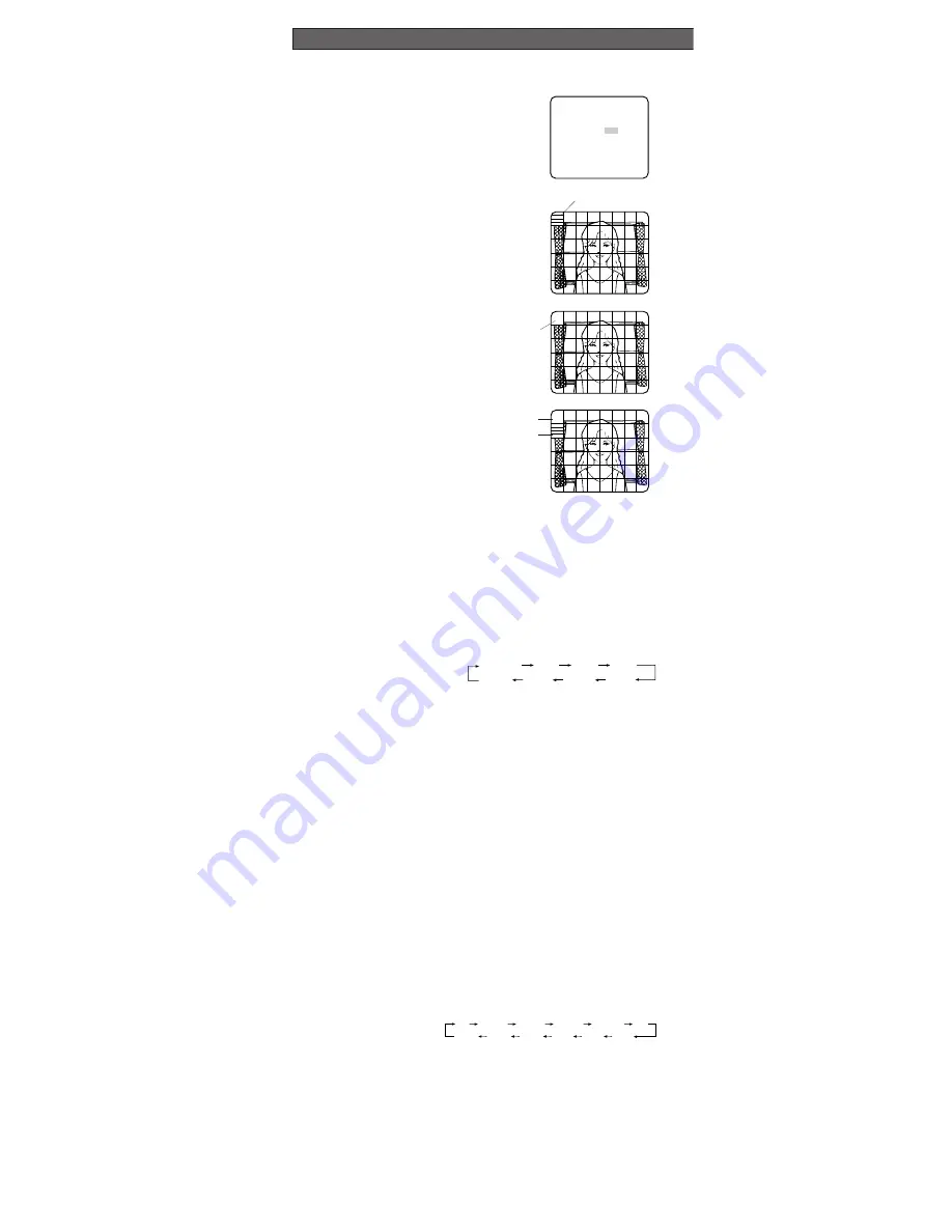
If ELC is selected, set MASK SET according to this procedure.

1. Move the cursor to SUPER-D2 and

select OFF. (When you select ELC,
SUPER-D2 is not available.) The MASK
SET appears on the menu.

2. Move the cursor to MASK SET and

press 

I

. The 48 mask areas appear

on the monitor screen. The cursor is
blinking in the upper left corner of the
screen.

3. Move the cursor to the area where

backlight is bright and press 

I

to

mask that area. The mask turns to
white. (When the cursor is moved on
an area that has already been masked,
the mask and cursor start blinking.)

4. Repeat step 3 to mask the desired

area. To cancel masking, move the
cursor to that area and press 

I

.

5. After masking is completed, press 

I

for 2 seconds or more. The ALC CONT
menu appears.

6. If you want to change the video output

level (picture contrast), move the “I”
cursor for LEVEL and adjust the level.

Note:

If ON is selected for SUPER-D2, a shadow (black line) may appear at the boundary

between the bright and the dim scene. This is a natural phenomenon and does not indi-
cate trouble.

3. Shutter Speed Setting (SHUTTER)

Note:

When ELC is selected for ALC/ELC on the CAM SET UP menu or ON is selected for

SUPER-D2 on the ALC CONT menu, this item is not available.
To select electronic shutter speed, select OFF for SUPER-D2 in the ALC CONT menu.

Move the cursor to SHUTTER and select the electronic shutter speed.

The preset values for SHUTTER (electronic shutter speed) change by pressing 

L

or 

M

as follows:
The factory default setting is ---.

4. Gain Control Setting (AGC ON (DNR-H, DNR-L)/OFF)

AGC (Automatic Gain Control) automatically controls the gain (an image brightness level).
Move the cursor to AGC and select automatic level adjustment ON (DNR-H), ON (DNR-L), or
OFF. The factory default setting is ON (DNR-H).

ON (DNR-H):

This setting raises the gain and brightens the image under low light con-

ditions.

ON (DNR-L):

This setting reduces an afterimage sometimes caused by a moving object

when ON (DNR-H) is activated.

OFF:

This setting does not control the gain.

Notes:

• When ON (DNR-L) is selected, noise can slightly increase than ON (DNR-H).
• DNR-H and DNR-L do not appear on the system status display of the connected equip-

ment.

5. Electronic Sensitivity Enhancement (SENS UP)

There are two modes for SENS UP.

AUTO:

If you select X10 AUTO, for example, the sensitivity is automatically raised to

X10 max. When AUTO is selected, AGC is automatically set to ON.

FIX:

If you select X32 FIX, for example, the sensitivity is raised to just X32.

The factory default setting is OFF.

Move the cursor to SENS UP and select the parameter for electronic sensitivity enhance-
ment.

The preset values for SENS UP (electronic sensitivity enhancement) change by pressing

L

or 

M

as shown right:

Notes:

• When ON is selected for SUPER-D2 in the ALC CONT menu, FIX is not available for this

item.

• When you select AUTO for SENS UP and ON for SUPER-D2, the SENS UP function has

priority so that the SUPER-D

2

function is not activated automatically.

• While the SENS UP function is selected, noise, spots or a whitish phenomenon may

appear in the picture when the sensitivity of the camera is increased. This is a normal
phenomenon.

SETTING PROCEDURES

X2 AUTO

OFF

X4 AUTO

X6 AUTO

X10 AUTO

X32 FIX

X10 FIX

X6 FIX

X4 FIX

X2 FIX

OFF

X16 FIX

   ** ALC CONT **
   BACK LIGHT COMP

SUPER-D2     OFF

MASK SET   

LEVEL        ...I.....
             -       +

RET  END

OFF (1/60)

1/100

1/10000

1/4000

1/2000

1/1000

1/250

1/500

Blinking

Blinking

Blinking

Turns to white

Summary of Contents for WV-CP470 Series

Page 1: ...to constitute a risk of electric shock to persons The serial number of this product may be found on the top of the unit You should note the serial number of this unit in the space provided and retain this instruction as a permanent record of your purchase to aid identification in the event of theft Model No Serial No SA 1966 SA 1965 N1101 1121 V8QA5915BN Printed in Japan N 19 Panasonic s WV CP470 ...

Page 2: ...ith a 4 pin male connector supplied as a standard acces sory Part No YFE4191J100 w Flange back Adjusting Ring Adjusts the back focal length and picture focus e Flange back Fixing Screw r Lens Option t Camera Mounting Screw Hole Mounts the camera onto a mounting bracket y Down Button K Moves the cursor downward and selects items in the CAM SET UP menu u Left Button L Moves the cursor to the left se...

Page 3: ... V AC power supply cord can be connected to this terminal The camera detects the power source auto matically 1 2 GND 1 2 AC 24V IN DC 12V IN 12 V DC 10 8 V 16 V Copper wire 24 22 20 18 size AWG 0 22mm2 0 33mm2 0 52mm2 0 83mm2 Resistance 0 078 0 050 0 030 0 018 Ω m Resistance 0 026 0 017 0 010 0 006 Ω ft Resistance of copper wire at 20 C 68 F Calculation of maximum cable length between camera and p...

Page 4: ...ns less than 450 g 0 99 lbs can be mounted on the camera If the lens is heavier both the lens and camera should be secured by the supporter C mount Less than 13 mm 1 2 CS mount Less than 8 mm 5 16 MOUNTING LENS FOCUS ADJUSTMENT Mounting from the Top Remove the mount adapter from the bottom of the camera by removing the two fixing screws Attach the mount adapter to the top as shown in the figure th...

Page 5: ...ing of the settings To edit the CAM SET UP menu change settings press J and K or L and M to move the cursor to SET UP DIS ABLE in the bottom line Press I SET UP DISABLE changes to SET UP ENABLE Move the cursor to END then to the item s you want to change Important Notice When the setup menu is closed after changing the parameters in the menu the new values are stored in the EEPROM Electrically Era...

Page 6: ...ss I The ALC CONT menu appears 2 Move the cursor to SUPER D2 and select ON 3 If you want to adjust the video output level move the I cursor for LEVEL Adjust to the desired level by pressing L or M ALC CONT BACK LIGHT COMP SUPER D2 ON LEVEL I RET END 1 Camera Identification CAMERA ID Setting You can use the camera identification CAMERA ID to assign a name to the camera The camera ID consists of up ...

Page 7: ...tically controls the gain an image brightness level Move the cursor to AGC and select automatic level adjustment ON DNR H ON DNR L or OFF The factory default setting is ON DNR H ON DNR H This setting raises the gain and brightens the image under low light con ditions ON DNR L This setting reduces an afterimage sometimes caused by a moving object when ON DNR H is activated OFF This setting does not...

Page 8: ...urb synchronization 4 After confirming that the cursor is on EXT VBS press I The phase adjustment menu appears on the moni tor screen 5 Supply the video output signal of the camera to be adjusted and the refer ence gen lock input signal to a dual trace oscilloscope 6 Set the oscilloscope to the horizontal rate and expand the horizontal sync portion on the oscilloscope 7 Move the cursor to H PHASE ...

Page 9: ...ity of the vertical phase of the camera video output signal may be disturbed 7 White Balance Setting WHITE BAL 7 1 Auto Tracing White Balance Mode ATW You can select one of three modes for white balance adjustment as follows The factory default setting is ATW1 ATW1 Auto Tracing White Balance 1 Move the cursor to WHITE BAL and select ATW1 In this mode the color temperature is monitored continuously...

Page 10: ...enu to prevent misinterpretation under low light con ditions with noise It takes about 0 2 seconds for the alarm signal to reach the VCR s alarm terminal after the camera detects the moving object The motion detector is not specifically intended to prevent theft or fire 9 Lens Drive Signal Selection LENS DRIVE This item is used to select the type of auto iris lens drive signal to be supplied to th...

Page 11: ...larm connections ON Black and white mode enabled OFF Color mode enabled The factory default setting is OFF 3 Select AUTO1 or AUTO2 using L or M 4 Press I The AUTO1 or AUTO2 menu appears on the monitor screen 5 Move the cursor to LEVEL and select the illuminance level using L or M LOW Color picture switches to black and white picture at approx 1 lx with F1 4 lens HIGH Color picture switches to blac...

Page 12: ...Hz 4 8 W Power Consumption WV CP474 24 V AC 60 Hz 4 3 W 12 V DC 440 mA Dimensions without lens 70 mm W x 55 mm H x 118 mm D 2 5 8 W x 2 3 16 H x 4 5 8 D Weights without lens WV CP470 0 46 kg 1 lbs without power cord WV CP474 0 45 kg 1 lbs Weights and dimensions indicated are approximate Specifications are subject to change without notice SPECIFICATIONS OPTIONAL ACCESSORIES Lenses WV LA2R8C3B WV LA...

Reviews: