background image

5

Precautions

• Do not operate the appliance beyond its specified tem-

perature, humidity or power source ratings. 
Do not use the appliance in an extreme environment
where high temperature or high humidity exists. Use the
appliance at temperatures 5 °C to +45 °C (41 °F
to 113 °F) and humidity below 85 %.
The input power source for this appliance is 120 V AC
60 Hz. 

• Avoid shock and vibration

Shock or vibration may damage the HDD.
The HDDs are fragile especially when the HDD motors
are revolving and the HDD POWER indicator lights. Be
sure to turn off either switch: the POWER switch on the
rear panel, or the HDD POWER switch inside the front
lid: before you mount the unit into a rack or dismount it. 
Do not move the HDD for 30 seconds after turning off
the power.

• Pay attention to static electricity

Put your hand on a metallic surface to discharge static
electricity before installation.
Do not touch components mounted on the HDD directly
with your hand.
Hold only the two sides of the HDD when installing.

General

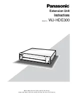
The extension unit WJ-HDE300 can contain up to four hard disk drives per unit to add available disk space to the digital disk
recorder WJ-HD316/WJ-HD309. Up to seven extension units can be connected to a digital disk recorder. The units can be
operated in RAID level 5* mode for high tolerance to disk error.

* RAID level 5 (Redundant Arrays for Independent Disks, independent data disks with distributed parity blocks)

RAID level 5 regards 3 or more drives as one drive, and it is possible to read data by automatically attaching error correc-
tion data even though one of the drives is broken. (It is impossible to read data if 2 or more drives are broken.)
RAID level 5 requires a minimum of 3 drives to implement.
When using the RAID function, logical disk size of the extension unit will be as below.
Logical disk size = Smallest size of the disk among the disks in the extension unit x (Number of the disks in the extension
unit - 1)  The actual space may be several percent lower than the logical space.

* Important

When set to RAID level 5, the digital disk recorder will not access the HDD preinstalled in it, but will access only the HDDs
in the extension unit.

• Avoid condensation on the surface of the HDD. 

If this happened, do not turn on the power of the appli-
ance and leave the appliance for around 2 hours.
Wait until the dew evaporates in any of the following
cases.

• The appliance is moved to a place significantly dif-

ferent in temperature or humidity.

• The appliance is moved out from an air-conditioned

room.

• The appliance is placed in an extremely humid

place.

• The appliance is placed in a room where a heater

has just been turned on.

• Consumable parts

Contact your dealer about replacement when the time
comes. 
A hard disk drive needs replacing after a certain length
(depends on the model) of operation.
Cooling fans also need replacing after around 
20 000 - 30 000 hours of operation.

• Do not block the ventilation opening or slots on the

cover.
To prevent the appliance from overheating, place it at
least 5 cm (2 inches) away from the wall. 

• Avoid placing the unit on an inclined surface.

Otherwise, malfunction or damage to the disk may
occur. Place the unit horizontally.

Summary of Contents for WJHDE300 - DIGITAL DISK RECORDER

Page 1: ...efore attempting to connect or operate this product please read these instructions carefully and save this manual for future use Extension Unit Instructions Model No WJ HDE300 WJ HDE300 Extension Unit...

Page 2: ...he limits for a Class A digital device pursuant to Part 15 of the FCC Rules These limits are designed to pro vide reasonable protection against harmful interference when the equipment is operated in a...

Page 3: ...our outlet consult an electrician for replacement of the obsolete outlet 10 Protect the power cord from being walked on or pinched particularly at plugs convenience receptacles and the points where th...

Page 4: ...4 Contents Important Safety Instructions 3 General 5 Precautions 5 Appearance 6 Replacing Mounting HDDs 9 Connections 14 Rack Mounting 16 Troubleshooting 18 Specifications 19 Accessories 19...

Page 5: ...is possible to read data by automatically attaching error correc tion data even though one of the drives is broken It is impossible to read data if 2 or more drives are broken RAID level 5 requires a...

Page 6: ...ctive HDD is the first faulty drive among the HDDs in the unit Red blink Indicates that the respective HDD is the second or subsequent faulty drive among the HDDs in the unit Orange red alternate blin...

Page 7: ...terminal of other equipment to avoid possible grounding loop and noise if required 0 Power switch POWER Turn on the power of the unit with this switch before turning on the power of the digital disk...

Page 8: ...ition Important Changing the MODE switch will not be accepted when the ERROR indicator lights red and or when HDD 1 4 indicate a system error status by lighting red and orange When this happens ask yo...

Page 9: ...of the exten sion unit 2 is added all HDDs of the extension unit 2 will be formatted Data readout will not be performed when the HDD posi tions are changed after once the system has been operated Pro...

Page 10: ...ody before touching the HDDs Put the conductive bag in which the HDD was packed on a soft surface and place the HDD on it with the cir cuit board side down 5 Fix the HDDs on the brackets 5 1 Slide the...

Page 11: ...ble on the next page to perform start up pro cedures Note that step 1 in the next page depends on how you have cut the motor power in case 1 or 2 men tioned in page 9 Take the steps in order depending...

Page 12: ...take a longer time to complete the data recovery Important Do not touch any button or switch during data recovery Otherwise data recovery will be canceled and will be incomplete During data recovery...

Page 13: ...ttach the front cover as it was 13 1 Align both the left edges of the front cover and the unit and then push the front cover onto the unit 13 2 Slide the front cover to the right 13 3 Tighten the two...

Page 14: ...mmended connection form Otherwise it may cause malfunction of the system Physical connections determine the unit number in a system for each unit Connect units with the recorder in numeric order as sh...

Page 15: ...00 5 WJ HDE300 4 WJ HDE300 3 WJ HDE300 6 WJ HDE300 7 EXT STORAGE IN IN IN IN IN IN IN OUT1 OUT2 POWER AC IN SIGNAL GND 1 2 IN OUT EXT POWER AC IN SIGNAL GND 1 2 IN OUT EXT OUT1 OUT2 OUT1 OUT2 Cable cl...

Page 16: ...etween the units for ventilation in a rack 1 2 1 2 1 2 1 2 1 2 1 2 1 2 IN OUT IN OUT IN OUT IN OUT IN OUT IN OUT IN OUT WJ HDE300 Unit 1 WJ HDE300 Unit 2 WJ HDE300 Unit 3 WJ HDE300 Unit 4 WJ HDE300 Un...

Page 17: ...ck securing it with four screws M5x12 not supplied 5 Turn on the power of the unit When the HDD POWER switch is turned off turn it on and attach the front cover as it was Cautions Make a space of 1U 4...

Page 18: ...he first faulty drive the blinking light means it is one of the later ones HDD access indicator light red and orange System fault Red and orange lighting of these four bits dis plays error status as s...

Page 19: ...350 mm D rubber feet exclusive 19 9 16 W x 3 7 16 H x 13 13 16 D Weight 7 2 kg 16 lbs not including hard disk drives Weight and dimensions indicated are approximate Specifications are subject to chan...

Page 20: ...cations Security Company Unit of Matsushita Electric Corporation of America Security Systems Group www panasonic com cctv Executive Office One Panasonic Way 3E 7 Secaucus New Jersey 07094 Zone Office...

Reviews: