background image

-32-

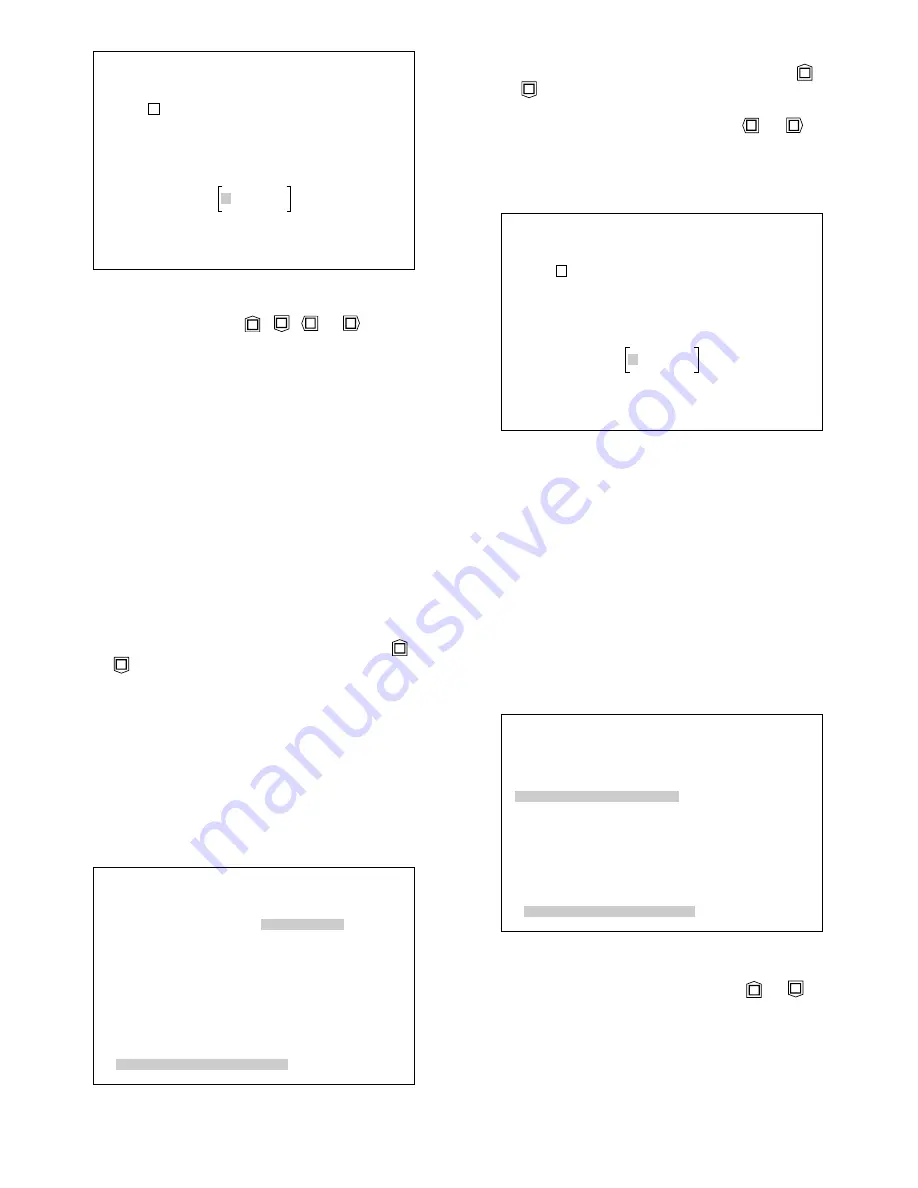
            LOGICAL FORMAT

 FORMAT             PASSWORD 

*

 VOLUME LABEL       

*

 DISC PASSWORD      

*

  START : PRESS SET KEY

2 Move the cursor to the FORMAT parameter in the

LOGICAL FORMAT menu by pressing the 

or

button.

3. Select PASSWORD by pressing the 

or 

but-

ton, then press the 

SET

button. The FORMAT PASS-

WORD table shown below appears on the monitor
screen.

           FORMAT PASSWORD

      A B C D E F G H I J K L M
      N O P Q R S T U V W X Y Z
      1 2 3 4 5 6 7 8 9 0

      CLEAR

                         (

SET)

4. Compose the Format Password as described for the

Setup Password above.

5. Press the 

SET UP/ESC

button for about 2 seconds

to apply the setting and exit the setup menu.

Disc Password Menu

1. Press the 

(–)

and 

(+)

buttons simultaneously for

about 2 seconds.  The LOGICAL FORMAT menu
shown below appears.

2. Move the cursor to DISC PASSWORD in the LOGI-

CAL FORMAT menu by pressing the 

or 

but-

ton, then press the 

SET

button.  The DISC PASS-

WORD table shown below appears on the monitor
screen.

            LOGICAL FORMAT

 FORMAT             EXECUTE
 VOLUME LABEL       

*

 DISC PASSWORD      

*

  START : PRESS SET KEY

            SET_UP PASSWORD

      A B C D E F G H I J K L M
      N O P Q R S T U V W X Y Z
      1 2 3 4 5 6 7 8 9 0

      CLEAR

                         (

SET)

3. Move the cursor on the desired character in the

table by pressing the 

or 

button.

4. Press the 

SET

button to pick up the character, and

place it it in the password area.

5. Repeat the above procedures 3 and 4 until the

password is completed.

6. If a wrong character is selected, press the (+) or (–)

button to move the cursor in the password area.
Then press the 

SET

button to overwrite the charac-

ter selected in the table.

Note:

Press the (+) button to move the cursor to the

right, or press the (–) button to move the cursor
to the left.

7. To clear the characters in the password area, move

cursor to CLEAR in the table by pressing the 

or

button, then press the 

SET

button.

8. Press the 

SET UP/ESC

button for about 2 seconds

to apply the setting and exit the setup menu.

Format Password Menu

1. Press the 

(–)

and 

(+)

buttons simultaneously for

about 2 seconds. The LOGICAL FORMAT menu
shown below appears.

Summary of Contents for WJDR200 - DIGITAL VIDEO RECORD

Page 1: ...AV Disc Recorder WJ DR200 Before attempting to connect or operate this product please read these instructions carefully ENGLISH FRANÇAIS ...

Page 2: ...he literature accompanying the appli ance The serial number of this product may be found on the rear of the unit You should note the serial number of this unit in the space provided and retain this book as a permanent record of your purchase to aid identification in the event of theft Model No Serial No CAUTION TO REDUCE THE RISK OF ELECTRIC SHOCK DO NOT REMOVE COVER OR BACK NO USER SER VICEABLE P...

Page 3: ...ng modes Single Shot Recording Records a single freeze pic ture Multi Shot Recording Records a continuous series of freeze pictures Time Lapse Recording Records freeze pictures at regular intervals FEATURES Easy picture search Three search modes for quick and easy picture search List Search Searches a list by recording date and time Thumbnail Search Searches displayed thumbnail images of recorded ...

Page 4: ...ong time from the AC outlet Insufficient charging of the bat tery may cause erasure of settings if the AC power supply should fail The battery if fully charged will back up the settings for 480 hours in an ordinary environment We recommend that you note down your settings and retain them Power or battery failure may erase settings you entered Do not expose the appliance to water or mois ture nor t...

Page 5: ... is on standby for recording 7 Disc indicator DISC Blinks lights red when the recording capacity of the DVD RAM disc is running low Blinks at 10 remaining space blinks rapidly at 5 and changes to steady light at 1 While overwriting in endless recording continues to turn on for two seconds and off for half a second MAJOR OPERATING CONTROLS AND THEIR FUNCTIONS R A M PUSH OPEN PUSH OPEN AV Disc Recor...

Page 6: ... temporarily pause playback Holding down the Pause button and pressing the REC button 31 will place the device into recording standby status 30 Reverse Playback button A A Press to play back frames in the reverse order they were recorded in Holding the button down will speed up reverse playback releasing it will restore the normal speed 0 2s 1 0s 0 2s An error has occurred on the disc in use The d...

Page 7: ...r from the Control Panel and Parallel Control port 49 Keep normally in OFF position 34 Stop button STOP Pressing the STOP button will terminate all modes of operation such as recording playback and setup 35 Open Close button OPEN CLOSE Press to slide the disc tray out or in for loading or unloading a disc Disabled while the Disc Cover 8 is closed 36 Increment button D D Pressing the D D button in ...

Page 8: ...ovided for recording and playback of audio sig nals 49 Parallel Control port PARALLEL CONTROL For connecting an outboard device used to remote control the Disc Recorder 50 Serial Control port SERIAL CONTROL For connecting a Personal Computer and the like to remote control the Disc Recorder 51 Camera Switching Output connector CAMERA SW OUT Outputs a pulse after each recorded frame 52 Terminal Boar...

Page 9: ... four rubber feet by removing the four screws from the bottom of the Disc Recorder OPERATE 2 Place the rack mounting brackets on both sides of the Disc Recorder and tighten them with the four supplied screws M4 X 10 OPERATE Cautions Do not block the ventilation opening or slots in the cover to prevent the appliance from over heating Always keep the temperature in the rack within 40 C 104 F Secure ...

Page 10: ...R used When the Disc Recorder is connected to several cameras for example through a multiplexer all camera inputs must be synchronized to obtain proper images Refer all connection work to qualified service personnel or system installers If you use the WJ DR200 AV Disc Recorder with a Sequential Switcher that is connected to non synchronized cameras 1 and switches their video output sequentially 2 ...

Page 11: ...R COMMERCIAL USE ONLY Made In Japan SIGNALGND 120V AC 60Hz OFF 125V 4 A POWER ON GND SENSOR IN ALARM IN ALARM RESET IN SERIES REC IN TIME ADJUST IN GND ALARM OUT ALARM RECOVER OUT ALARM REC REC DISC BUZZER OUT SYSTEM ERROR OUT THERMAL ERROR OUT TIME ADJUST OUT SERIES REC OUT LED MONITOR CAMERA SW OUT AUDIO PARALELL CONTROL SERIAL CONTROL IN OUT S VIDEO OUT S VIDEO VIDEO OUT VIDEO IN B A SER NO 6ZA...

Page 12: ...rders TIME ADJUST IN Connects a time adjust input from an external source to synchronize the Disc Recorder s internal clock When this input is detected the time is adjusted to an accuracy of 30 seconds Output Terminals ALARM OUT Sends an alarm signal in response to an alarm input ALARM RECOVER OUT Sends an alarm recover signal in response to the alarm reset signal received when the ALARM RESET but...

Page 13: ...me way as with the control buttons on the recorder s front panel 13 12 11 10 9 8 7 6 5 4 3 2 1 25 24 23 22 21 20 19 18 17 16 15 14 1 2 3 4 5 6 7 8 9 10 11 12 13 Ground Ground ALARM REC STANDBY UP STOP SET UP ESC LOCK INDEX LEFT SET PLAY RIGHT PAUSE Pin No Designation 14 15 16 17 18 19 20 21 22 23 24 25 FIND REC FORMAT DOWN OPEN CLOSE FORMAT PLAY BACK SELECT Not Used REVERSE PLAY ALARM RESET Not Us...

Page 14: ...ng of video data to a personal computer 1 2 3 4 5 6 7 8 12 17 18 20 23 FG TxD RxD RTS CTS DSR SG DCD T B R B R A DTR T A Frame Ground Transmit Data Receive Data Request to Send Clear to Send Data Set Ready Signal Ground Data Carrier Detect Transmit Data RS 485 Receive Data RS 485 Receive Data RS 485 Data Terminal Ready Transmit Data RS 485 Pin No Designation out in out in in in out in in out out I...

Page 15: ...ROR OUT TIME ADJUST OUT SERIES REC OUT LED MONITOR GND SENSOR IN ALARM IN ALARM RESET IN SERIES REC IN TIME ADJUST IN GND ALARM OUT ALARM RECOVER OUT ALARM REC REC DISC BUZZER OUT SYSTEM ERROR OUT THERMAL ERROR OUT TIME ADJUST OUT SERIES REC OUT LED MONITOR Connection for Alternate Time Lapse Recording Series Recording Connection The WJ DR200 can be set up for automatic serial recording by connect...

Page 16: ...AIN menu press the SET UP ESC button for about 2 seconds to apply the setting and exit the setup mode Note If alarm is activated during the setup opera tion the setup menu disappears and the display returns to the normal picture Any settings previ ously made take effect even if the SET UP ESC button was not pressed The following buttons are valid in the setup menu UP Moves the cursor upward DOWN M...

Page 17: ...WORD START UP STATUS CLOCK SET SERIAL PORT SET UP VIDEO INPUT STATUS DISPLAY ALARM DISPLAY DISPLAY POSITION SERIES RECORD SERIES RECORD OUTPUT SYSTEM INFORMATION Page 16 Page 16 DISC LED FUNCTION BUZZER VIDEO PIXEL VIDEO QUALITY AUDIO RECORD CAPTURE MODE ENDLESS RECORD SIGNAL TYPE ALARM RECOVER FUNCTION ALARM TIMER DURATION ALARM BUZZER ALARM LABEL SENSOR LABEL DELAY TIME PROGRAM TIMER ON FIRST RE...

Page 18: ...SERIES REC OUT CLOSE DISC LED FUNCTION FULL BUZZER ON To select an item or parameter in the SYSTEM menu 1 Move the cursor to the desired item or parameter by pressing the or button 2 Press the or button to select the desired parameter 3 Press the SET button to execute the selection or display a submenu for an item with the mark 4 Press the SET UP ESC button to return to the MAIN menu if desired Cl...

Page 19: ...essing the or button 3 Select the desired port number 01 to 16 by press ing the or button to identify the Disc Recorder when multiple recorders are connected in the system The default setting is 01 4 Move the cursor to the SIGNAL TYPE parameter by pressing the or button 5 Select one of the interface modes shown below by pressing the or button RS 232C RS 232C VCR mode or RS 485 The default setting ...

Page 20: ... set number 4 If you are connecting the WJ DR200 AV Disc Recorder to the Spot Output or Camera Output of a sequential switcher or video multiplexer to which a line locked camera is connected be sure to select the CAMERA TYPE parameter Line Lock The default setting is COLOR 8 Move the cursor to the INPUT CHECK parameter by pressing the or button 9 Press the or button to display the video selected w...

Page 21: ...ameter for Alternate Time Lapse Recording page 37 The default setting is CLOSE Disc LED Function Setup This item lets you specify the conditions for output of the signal from the DISC LED MONITOR terminal on the Terminal Board located on the rear of the Disc Recorder See page 10 1 Move the cursor to the DISC LED FUNCTION para meter in the SYSTEM menu by pressing the or button 2 Select either SPACE...

Page 22: ...cture quality ROUGH For lower picture quality The default setting is FINE Audio Recording Setup This item lets you enable or disable audio recording Audio recording is available depending on the selected recording mode as shown below A A B Recording start Recording end Multi Shot Time Lapse Recording A Single Shot Recording A Single Shot Recording A B 1st shot 2nd shot Last shot Continuous recordi...

Page 23: ...ail able in REC MODE 2 1 Move the cursor to the ENDLESS parameter in the REC MODE menu by pressing the or but ton 2 Select either ON or OFF by pressing the or button ON Continues recording when the disc is full by overwriting the oldest data OFF Stops recording when the disc is full The default setting is OFF 1 Multi Shot Recording Setup This menu lets you make the necessary settings for Multi Sho...

Page 24: ...are not available in MODE 2 1 Move the cursor to the CAPTURE MODE parameter in the REC MODE menu by pressing the or button Pre Post Frames This item lets you specify the number of pre frames A pre frame is a frame recorded during standby for manual recording or prior to input of the alarm signal in alarm recording A post frame is a frame recorded after the REC button was pressed in manual recordin...

Page 25: ... SEN SOR IN terminal The maximum number of pre frames is set with the PRE FRAMES parameter above 1 Move the cursor to the PRE FRAMES parameter in the TIME LAPSE menu by pressing the or button 2 Select the number of pre frames to be recorded by pressing the or button 2 Select TIME LAPSE by pressing the or button then press the SET button The TIME LAPSE menu shown below appears on the monitor screen...

Page 26: ...Recording Pattern This item is available only if the CAMERA INPUT parameter in the VIDEO INPUT menu is set to A B CAMERA ID OFF It lets you select recording of pre and post frames from input A and or B when there is sensor input from the SENSOR IN terminal 1 Move the cursor to the POST REC PATTERN parameter in the TIME LAPSE menu by pressing the or button 2 Select the desired recording input for p...

Page 27: ...REC ALARM menu by pressing the or button 2 Select the desired mode by pressing the or button 720 480 3DIM ON High resolution non blur pic ture 720 480 3DIM OFF High resolution picture 720 240 Lower resolution but higher number of frames The default setting is 720 480 3DIM ON Note The parameter 720 240 is fixed if the A CAMERA ID ON is selected for the CAMERA INPUT parameter in the VIDEO INPUT menu...

Page 28: ...m by pressing the or button 2 Select a parameter by pressing the or but ton 3 Press the SET UP ESC button to return to the previ ous MAIN menu if desired Alarm Input Signal Setup This item lets you select either Normally Open or Normally Closed for alarm or sensor input 1 Move the cursor to the SIGNAL TYPE parameter in the ALARM RECORD menu by pressing the or button 2 Select either CLOSE or OPEN b...

Page 29: ...tton 2 Select an alarm duration between 1 second and 5 minutes as shown below by pressing the or button 1 sec 30 sec 1 min 2 min 3 min 4 min 5 min The default setting is 2 sec Alarm Buzzer Setup This item lets you enable or disable the buzzer sound in response to alarm input 1 Move the cursor to the BUZZER parameter in the ALARM RECORD menu by pressing the or button 2 Select ON or OFF by pressing ...

Page 30: ...mbers displayed in ascending order starting with the oldest one The default setting is NEW Skip Records Setup This item lets you select the number of records skipped each time the Advance Record or Reverse Record button is pressed during playback 1 Move the cursor to the SKIP RECORDS parameter in the SEARCH PLAY menu by pressing the or button 2 Select the number of records quantity to be skipped a...

Page 31: ...ect the maximum number of thumbnail pictures displayed in the search window 1 Move the cursor to the THUMBNAIL parameter in the SEARCH PLAY menu by pressing the or button 2 Select either 8 or 16 by pressing the or but ton 8 Displays a maximum of 8 thumbnail pictures 16 Displays a maximum of 16 thumbnail pictures The default setting is 8 PLAY Button Setup This item lets you select the number of rec...

Page 32: ...ter the DVD drive has been deactivated System Information Menu This menu allows you to specify the sleep operation mode of the DVD drive and lists status information for the Disc Recorder 2 Move the cursor to ALARM LABEL or SENSOR LABEL in the ALARM RECORD menu by pressing the or button then press the SET button The label editing menu shown below appears A B C D E F G H I J K L M N O P Q R S T U V...

Page 33: ... button then press the SET button The label editing menu shown below appears on the monitor screen A B C D E F G H I J K L M N O P Q R S T U V W X Y Z a b c d e f g h i j k l m n o p q r s t u v w x y z 1 2 3 4 5 6 7 8 9 0 _ CLEAR SET 3 Compose the Volume Label as described for the Alarm Label above 4 Press the SET UP ESC button to apply the setting and return to the previous LOGICAL FORMAT menu P...

Page 34: ...rs on the monitor screen LOGICAL FORMAT FORMAT EXECUTE VOLUME LABEL DISC PASSWORD START PRESS SET KEY SET_UP PASSWORD A B C D E F G H I J K L M N O P Q R S T U V W X Y Z 1 2 3 4 5 6 7 8 9 0 CLEAR SET 3 Move the cursor on the desired character in the table by pressing the or button 4 Press the SET button to pick up the character and place it it in the password area 5 Repeat the above procedures 3 a...

Page 35: ...l the new password is completed 5 To delete characters in the password area move the cursor to CLEAR in the table by pressing the or button then press the SET button 6 Press the SET UP ESC button for about 2 seconds to apply the setting and exit the setup menu DISC PASSWORD A B C D E F G H I J K L M N O P Q R S T U V W X Y Z 1 2 3 4 5 6 7 8 9 0 CLEAR SET 3 Compose the Disc Password as described fo...

Page 36: ...e completed in about 30 seconds 9 To stop formatting press the SET UP ESC button for about 2 seconds 10 To unload the disc press the OPEN CLOSE button to slide out the tray Then press the OPEN CLOSE button again to slide in the tray 11 Close the Disc Cover and Control Panel OPERATING PROCEDURES PROTECT PUSH OPEN DVD RAM Disk OPERATE SET T L MODE FORMAT OPEN CLOSE WRITE ENABLED Disc Tray SET UP ESC...

Page 37: ...gress as this could damage the disc STATUS DISPLAY The Status Display window shows the system status of the Disc Recorder It is displayed on the monitor screen during recording and playback and contains the follow ing information 012345aMA REC P CAPTURE RATE AUG 1 98 14 15 05 ALARM001 100 q Record Number 0 1 2 3 4 5 a S A 1 2 3 4 1 6 digit number of the record currently being recorded or played ba...

Page 38: ...8 14 15 05 100 Manual Record with Standby 1 Press the REC button while holding down the PAUSE button yREC is displayed in the lower center of the monitor screen and the recorder stands by for recording in the selected mode 2 Press the REC button 5REC is displayed in the lower center of the monitor screen and recording in the selected mode starts 3 When recording is completed the recorder auto mati...

Page 39: ...g set the ENDLESS parameter in the REC MODE 1 menu to OFF Select the same recording method when operat ing multiple recorders in Alternate Alarm Recording or Auxiliary Alarm Recording Alternate Alarm Recording Refer to Series Recording 1 on page 13 for connections 1 In the SYSTEM menu of both recorders set the START UP STATUS parameter to ALARM REC SYSTEM CLOCK AUG 1 98 0 00 START UP STATUS ALARM ...

Page 40: ...apse Alarm Recording In Manual or Auto Start Time Lapse Recording this function starts recording according to the selected setup for this mode when an alarm signal is received from the ALARM IN terminal on the Terminal Board Refer to the MANUAL REC ALARM menu on page 24 for the necessary settings The record number is updated at the start and end of Manual Time Lapse Alarm Recording The recording d...

Page 41: ...or button repeatedly The input channels or camera ID numbers are dis played in the lower right corner of the monitor screen as shown below 012345aMA PLAY P CAPTURE RATE AUG 1 98 14 15 05 A T L MODE FORMAT 2 Press the PLAY BACK SELECT button The pic ture selected in step 1 by pressing the or but ton is played back in the mode paused with the PAUSE button 3 To release this mode select AB or ALL by p...

Page 42: ...tor screen by pressing the or button 4 Press the PLAY or button to play back the selected record forward or backward 5 To display the list again press the INDEX button again 6 To stop playback or release the search function press the STOP button Thumbnail Search This function lets you search for specific records by observing thumbnail images of recorded pictures Note Confirm that the ALARM REC ind...

Page 43: ...s found playback starts immediately If a matching record is not found a list of records including the record with the closest matching number or date is displayed The closest match is blinking 6 Press the SET button to play back the blinking record 7 To stop playback or release the find function press the STOP button Notes Pressing the FIND button in the Thumbnail window will display the thumbnail...

Page 44: ...2 35 30 012341 S AUG 1 98 12 25 30 HIDE RECORD NO 01238 4 Press the or button to scroll to the next or previous page 5 Select the record you wish to deny access to by pressing the or button The selected record blinks 6 Press the SET button to toggle the recording date and time of the selected record on and off Playback of the record is disabled when the record ing date and time are not displayed 7...

Page 45: ...e table above int Truncated to the decimal point 2 With Audio 1007950 Number of records int P X A x N int 1 003 0 039 x N 1 A Audio data size see explanation for A under Time Lapse Recording Time Number of Recorded Frames Note The number of recorded frames varies slightly depending on the images recorded 1 1 ch recording Number of frames 720 240 43 APPENDIX 720 480 FINE 34 18 NORMAL 22 11 ROUGH 14...

Page 46: ...398 40 498 20 598 00 Recording Time in Time Lapse Recording hours minutes 0 03 0 07 0 10 0 17 0 20 0 33 0 50 1 2 3 4 5 10 15 20 25 30 Audio ON Pixel Number 720 240 FINE NORMAL ROUGH Audio OFF FINE NORMAL ROUGH 0 29 0 45 1 01 0 30 0 50 1 09 0 58 1 32 1 28 2 18 2 26 3 52 2 46 4 17 4 38 7 09 6 38 9 57 11 38 16 25 19 14 25 22 23 56 29 56 27 54 33 52 31 00 36 46 38 40 42 53 42 00 45 20 44 00 46 40 45 3...

Page 47: ...INFO 00 0 0 0 00 FM CON JPEG SCSI CON AUDIO VIDEO DEC SERIAL I O DRAM DVD DRIVE SRAM PD 2 LD D100 M STRM CON 4 Pressing the following buttons will display your password within brackets for a short period of 5 seconds To check your SETUP Password Press the and STOP buttons simultaneously with the LOCK switch in ON position To check your FORMAT Password Press the FORMAT buttons and simultaneously wi...

Page 48: ... into the tray Refer to the operating instructions of the cleaning disc for details 5 Press the OPEN CLOSE button on the Control Panel to slide in the tray Cleaning will start automatically 6 After 30 seconds the message DRIVE ERROR appears on the monitor screen and the BUSY indi cator begins to blink in green 7 Press the OPEN CLOSE button to slide out the tray then remove the cleaning disc 8 Pres...

Page 49: ...ard jack Terminal Board Sensor Input Pulse width 100 ms or more Normally open or normally closed selectable Alarm Input Pulse width 100 ms or more Normally open or normally colosed selectable Alarm Reset Input Pulse width 100 ms or more Low active Series Record Input 1 circuit Time Adjustment Input Pulse width 100 ms or more Low active Alarm Output Switched by alarm output level selector 1 Alarm R...

Page 50: ... 48 STANDARD ACCESSORY AC Power Cord 1 pc ...

Page 51: ...c Way Secaucus NJ 07094 201 348 7303 Southern 1225 Northbrook Parkway Suite 1 160 Suwanee GA 30024 770 338 6838 Midwest 1707 North Randall Road Elgin IL 60123 847 468 5211 Western 6550 Katella Ave Cypress CA 90630 714 373 7840 PANASONIC CANADA INC 5770 Ambler Drive Mississauga Ontario L4W 2T3 Canada 905 624 5010 PANASONIC SALES COMPANY DIVISION OF MATSUSHITA ELECTRIC OF PUERTO RICO INC San Gabriel...

Reviews: