background image

8

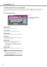
About the operation of on-screen keyboard

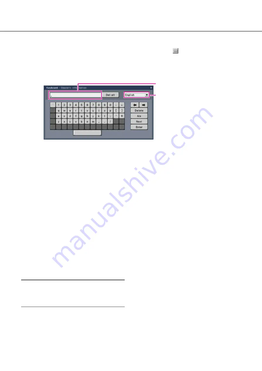
Use the on-screen keyboard to enter characters for the setting items. When clicking the [

] icon beside the entry field, the on-

screen keyboard will be displayed, and it will become possible to enter characters by clicking the character keys on the key-
board.

On-screen keyboard screen

[Del all] button

Deletes all the characters in the entry field.

[

]/[

] button

Move the cursor in the entry field to either direction.

[Delete] button

Deletes a character pointed by the cursor in the entry field.

[A/a] button

This button changes the characters to be entered between 
capital letters and small letters.

[Next] button

Changes the keys to be displayed for character entry.
The displayed keys are changed as follows:
 

Keys for the language selected by the language selec-
tion pull-down menu 

 Combination characters 


Special characters

[Enter] button

Determines the entered characters and closes the on-screen 
keyboard.

Note:

•  Basic operations are also applied to the "Login" window 

and registration window for license.

•  Click the [×] button to close the window without deter-

mining the entered characters.

Entry field

Language selection pull-down menu

Click the [

] button to select the language 

for character entry.

Introduction

 (continued)

Summary of Contents for WJ-NX400K/GJ

Page 1: ...sonic support website https security panasonic com download Before attempting to connect or operate this product please read these instructions carefully and save this manual for future use The model...

Page 2: ...a mouse 15 Connection of monitors 16 Connection of a PC 17 Connection of extension units 19 How to use the terminals of the ALARM CONTROL 20 How to use the terminals of the ALARM IN 24 Time and polari...

Page 3: ...Camera setup Camera Set up recording events REC event Advanced setup Configure the settings relating to monitors Monitor Configure the settings relating to network Network Configure the settings relat...

Page 4: ...work cameras hereinafter cameras and their versions Refer to the Panasonic support website https security panasonic com support for latest information about the compatible cameras and functions to be...

Page 5: ...urn black About HDD Unit To install a hard disk drive in the recorder it is necessary to assemble an HDD unit encase the hard disk drive in the HDD canis ter The HDD unit is designed to easily install...

Page 6: ...is product near noise sources If the cables are placed near noise sources such as fluores cent lamps noises may be produced In this case rewire avoiding the noise sources or move the product to a plac...

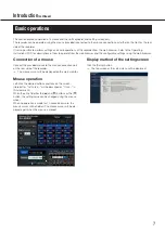
Page 7: ...changed using the mouse wheel When no operation is made for 10 seconds or more the mouse cursor will be hidden The mouse cursor will be dis played again when the mouse is moved This section explains o...

Page 8: ...ield A a button This button changes the characters to be entered between capital letters and small letters Next button Changes the keys to be displayed for character entry The displayed keys are chang...

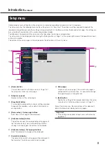
Page 9: ...etup pages Easy Start button It is possible to configure the minimum settings required to operate the recorder such as date time and cam era registration Basic setup Setup page buttons Each Basic setu...

Page 10: ...ion unit if connected Turn on the power of the recorder Register the Registration Key of the recorder If necessary register the Registration Key for the Additional Camera Kit or the Secure Communicati...

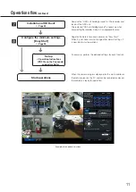
Page 11: ...he removed HDD unit holding bracket is necessary when transporting the recorder Keep it in an appropriate place Register the date time and cameras on Easy Start When it is not necessary to change othe...

Page 12: ...license according to the Additional Camera Kit option To use the secure function get the registration key number of the additional secure license according to the Secure Communication Kit option Each...

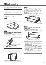
Page 13: ...erheating The recorder weighs over 10 kg 22 1 lbs Be careful not to drop the recorder when installing it into a rack Dropping may cause damage deformation of the recorder or injury Install the recorde...

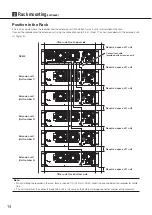
Page 14: ...pace of 1 unit Require a space of 1 unit Connection cable provided with extension unit Extension unit Unit number 1 Extension unit Unit number 2 Extension unit Unit number 3 Extension unit Unit number...

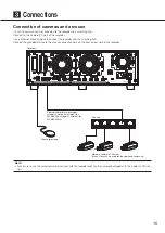
Page 15: ...ct the provided mouse to the mouse connection port on the front or rear side of the recorder Recorder Ethernet cable locally procured category 5e or better straight for WJ NX400K category 7 straight f...

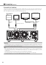
Page 16: ...tered the main or sub monitor displays image of a channel from 1 to 64 channel When the additional camera license is registered the image will be displayed only on the web browser of the PC The main a...

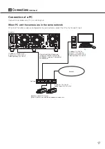
Page 17: ...twork camera x 128 max When 2 licenses are used for the additional camera kit PC IP address 192 168 0 250 Subnet mask 255 255 255 0 Default gateway 192 168 0 1 Ethernet cable locally procured category...

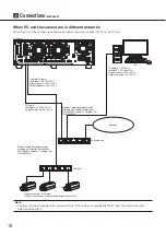
Page 18: ...aight for WJ NX400K G Ethernet cable locally procured category 5e or better straight for WJ NX400K category 7 straight for WJ NX400K G Camera PC port IP address 192 168 0 250 Subnet mask 255 255 255 0...

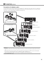
Page 19: ...ber 1 Extension unit unit number 2 Extension unit unit number 3 Extension unit unit number 4 Extension unit unit number 5 Attach a cable clamp to each connection cable Attach a cable clamp to each con...

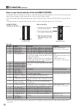
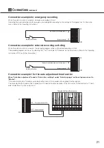
Page 20: ...signal is output at the setting time of the recorder and the time of other equipment is adjusted to the time of the recorder Input Non voltage make contact input Output Open collector output 24 V DC m...

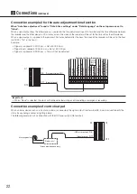
Page 21: ...recording mode switching input C1 C12 D11 Connection example 1 for the auto adjustment time function When Auto time adjustment found in Date time settings under Date Language on the setup menu is set...

Page 22: ...not be adjusted Signal ground Time adjustment I O C5 C1 C11 D1 D12 Terminal of the other device Signal ground Sensor input Alarm input Alarm reset input Series recording input Time adjustment input Si...

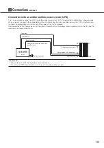
Page 23: ...y for the recorder After completion of the internal processing the signal will be output from the outage processing end output to the UPS and the recorder will be ready to be shut off Uninterruptible...

Page 24: ...lly inserted into the terminal hole Loosen the screw of the desired terminal on the terminal plug Mount the terminal plug with the cable connected on the alarm input terminal socket on the back Pin ar...

Page 25: ...dance with the settings When an alarm device such as a buzzer a lamp etc is installed outside connect them to the Alarm output terminal pin no C2 Alarming device Relays etc Attached when necessary Sen...

Page 26: ...ration has passed or the camera reset L active Recording error output At an error occurrence until the period selected for Error out put duration has passed L active Recorder error output At an error...

Page 27: ...rder will light the system check will start and the startup window will be displayed on the main monitor Important Never turn off the power of the recorder during startup Insert the power cord fully i...

Page 28: ...ter an administrator a password and a password confir mation following the instruction on the display and click Registration Important Change the password periodically Precautions on storing the admin...

Page 29: ...ditional camera kit is added The added cameras shall be registered on Easy start Page 35 or on the Camera registration tab Each setting value is the default Configure each setting according to your ne...

Page 30: ...tional camera license obtained in step 1 to the Registration Key 1 2 fields under Additional camera on the Registration of license page shown in step 5 To use the secure function click the Setup butto...

Page 31: ...drive Use an anti static mat and an anti static grounding strap when installing replacing the hard disk drives When installing hard disk drives use a low torque powered screwdriver or a torque screwd...

Page 32: ...ithout knocking it against anything and without knocking against HDD units which are already inserted Push the upper part of the lever securely until it hits the protruding section at the back side of...

Page 33: ...number on the HDD slot Lift up the lever on the HDD unit while holding down the removal knob and then insert the HDD unit all the way into the HDD slot Insert the HDD unit carefully without knocking i...

Page 34: ...management page will be displayed Step 3 Confirm that the connected HDD is displayed on the HDD management page Step 4 Click Execute next to Format HDD on the HDD management page HDD format screen is...

Page 35: ...operate the recorder such as the date time camera registration recording can be config ured on the setup menu the Quick setup menu Easy Start First configure the minimum settings on Easy Start and to...

Page 36: ...as well mark the Also change camera titles checkbox New button Usually use it with no camera registered in the recorder Detects all the connected cameras The models and results of the detected camera...

Page 37: ...e selected If a camera whose compression method is MJPEG is included MJPEG camera is set to 5 ips even if 10 ips 15 ips 30 ips is set by slider bar of frame rate set ting You can confirm the current s...

Page 38: ...a image on the monitor does not appear please use the browser on your PC 5 Part of the displayed image is missing This phenomenon is caused by dispersion of display area on the monitor This is not a m...

Page 39: ...the extension unit Turn on the extension unit before turning on the power of the recorder 27 When using a circuit breaker or equivalent device to turn on off the power of the whole system at one time...

Page 40: ...ronment For more information about collection and recycling please contact your local municipality Penalties may be applicable for incorrect disposal of this waste in accordance with national legislat...

Reviews: