background image

8

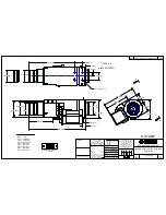
4.2.2.

Removal of the Adjustment Dial
Cover

Fig. L2

4.2.3.

Removal of the Lens Barrel Unit

Fig. L3

Summary of Contents for VW-CLT1P

Page 1: ...olour H Gray Type 4 TABLE OF CONTENTS PAGE PAGE 1 Specifications 2 2 Location of Controls and Components 3 3 Troubleshooting Guide 6 4 Disassembly and Assembly Instructions 7 4 1 Disassembly Flow Char...

Page 2: ...2 1 Specifications...

Page 3: ...nt 3 Lens 4 Adjustment dial cover 5 Protective glass rear 6 Camera body attachment part convex 1 3 2 6 4 5 7 Vertical position adjustment dial 8 Vertical alignment adjustment dial 9 Horizontal image p...

Page 4: ...nd the black horizontal line are within the red guidelines and adjustment is not required touch EXIT and proceed to Step 11 Perform the adjustment in a bright location where the horizontal line for ad...

Page 5: ...hen the 3D Conversion Lens is attached the zoom position is fixed and the zoom operation is disabled When recording in 3D the image will appear with gray frame around it The gray frame will be recorde...

Page 6: ...6 3 Troubleshooting Guide...

Page 7: ...t Fig L1 No Item Fig Removal 1 Bottom Case Front Case Unit Fig L1 5 Screws A Bottom Case Front Case Unit 2 Adjustment Dial Cover Fig L2 Cover Sheet 1 Screw B 2 Screws C Adjustment Dial Cover 3 Lens Ba...

Page 8: ...8 4 2 2 Removal of the Adjustment Dial Cover Fig L2 4 2 3 Removal of the Lens Barrel Unit Fig L3...

Page 9: ...9 Fig L4 4 2 4 Removal of the Fixing Base and Fixing Dial Fig L5...

Page 10: ...10 4 2 5 Removal of the Horizontal Position Adjustment Dial Unit Fig L6...

Page 11: ...11 5 Exploded View and Replacement Parts List 5 1 Casing Parts Section...

Page 12: ...12 5 2 Packing Accessories Section...

Page 13: ...B406 XQN2 BJ3FN SCREW 1 B407 XQN2 BJ3FN SCREW 1 B408 XQN16 B3FN SCREW 1 B409 XQN2 BJ4FJK SCREW 1 B410 XQN2 BJ4FJK SCREW 1 B411 XQN2 BJ4FJK SCREW 1 B412 VHD1776 SCREW 1 B413 VHD1776 SCREW 1 B414 XQN2 B...

Reviews: