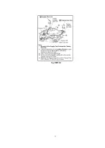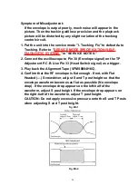
5. Confirm and readjust the A/C Head height.
6. Confirm and readjust Screw C (Azimuth) on the A/C head so that
the output audio becomes is maximum.
8.2.2.1.4. A/C HEAD HORIZONTAL POSITION ADJUSTMENT
Purpose:
To adjust the Horizontal Position of the A/C Head.
Symptom of Misadjustment:
If the Horizontal Position of the A/C Head is not properly adjusted,
maximum envelope can not be obtained at the Neutral Position of
the Tracking Control Circuit.
1. Put the unit into the service mode "I. TRACKING FIX" to defeat
Auto Tracking. Refer to "
SERVICE MODE SPECIFICATION (SELF-
DIAGNOSTIC SYSTEM)
" in "SERVICE NOTES."
2. Connect the oscilloscope to Pin 30 (Envelope signal) on the TP
Adjustment P.C.B. Use Pin 33 (Head Switch signal) as a trigger.
3. Play back the Alignment Tape (VFMS0004H6C).
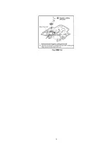
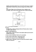
4. Set the Screwdriver into the Hole (A) as shown.
Fig. M6-1
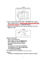
5. Slowly move the A/C Head Unit to the direction "A" or "B" as
shown so that the envelope is at maximum.
Fig. M6-2
87
Summary of Contents for VM-D101
Page 10: ...Fig 2 2 2 Install the Lock Screw in the Hole Threaded Hole for Lock Screw 10 ...
Page 12: ...12 ...
Page 13: ...13 ...
Page 14: ...14 ...
Page 15: ...15 ...
Page 16: ...16 ...
Page 17: ...6 1 5 DESCRIPTION OF EMERGENCY INDICATIONS 17 ...
Page 22: ...Fig 5 2 6 1 8 4 Signal description on TP Adjustment P C B 40P VFKW0123B Fig 5 3 1 22 ...
Page 23: ...Fig 5 3 2 23 ...
Page 24: ...Fig 5 3 3 24 ...
Page 32: ...7 1 2 2 EVR Cover Side Case L Unit Fig D3 32 ...
Page 33: ...7 1 2 3 Sensor Shield Case Lens Unit Fig D4 33 ...
Page 34: ...7 1 2 4 Main C B A Fig D5 7 1 2 5 VCR Mechanism Chassis Ass y Side Case R Unit Fig D6 34 ...
Page 35: ...7 1 3 LCD PORTION For model with LCD Monitor 7 1 3 1 Cassette Cover Unit Fig D7 1 35 ...
Page 36: ...7 1 3 2 Relay C B A Cassette Frame Fig D7 2 36 ...
Page 38: ...7 1 3 6 LCD Lamp Unit Fig D7 6 38 ...
Page 39: ...7 1 4 SIDE CASE L PORTION 7 1 4 1 EVF Unit Color EVF Unit Fig D8 1 39 ...
Page 40: ...7 1 4 2 Side L FPC Unit Fig D8 2 40 ...
Page 41: ...7 1 5 EVF PORTION For model with Monochrome EVF 41 ...
Page 43: ...7 1 6 COLOR EVF PORTION For model with Color EVF 43 ...
Page 46: ...Fig D11 2 46 ...
Page 47: ...7 1 8 LENS PORTION B 7 1 8 1 Lens Piece Unit Fig D12 1 47 ...
Page 49: ...7 1 9 2 Top Operation Unit Fig D13 2 7 1 9 3 Battery Catcher Unit Fig D13 3 49 ...
Page 52: ...7 3 2 Inner Parts Location 7 3 2 1 TOP VIEW Fig DM1 1 52 ...
Page 53: ...7 3 2 2 BOTTOM VIEW Fig DM1 2 7 3 3 STOP Position Confirmation Fig DM2 53 ...
Page 55: ...Fig DM3 2 55 ...
Page 56: ...7 3 5 Cylinder Unit Fig DM4 1 1 56 ...
Page 57: ...Fig DM4 1 2 57 ...
Page 58: ...7 3 6 Cylinder Head Amp F P C Bugle Chip Fig DM4 2 7 3 7 P C B Angle Fig DM5 58 ...
Page 59: ...7 3 8 Mechanism F P C Unit Fig DM6 1 59 ...
Page 60: ...Fig DM6 2 60 ...
Page 61: ...7 3 9 Tension Unit Reel Table Unit Fig DM7 1 61 ...
Page 62: ...Fig DM7 2 62 ...
Page 63: ...7 3 10 Rev Clutch Fig DM8 63 ...
Page 64: ...7 3 11 Take Gear Rev Brake Arm Unit Fig DM9 1 Fig DM9 2 64 ...
Page 65: ...7 3 12 A C Head Unit Fig DM10 65 ...
Page 66: ...7 3 13 Capstan Belt Fig DM11 66 ...
Page 67: ...7 3 14 Capstan Unit Fig DM12 67 ...
Page 68: ...7 3 15 Idle Arm Unit Fig DM13 68 ...
Page 69: ...7 3 16 Mechanism Support Angle Fig DM14 69 ...
Page 70: ...7 3 17 Reduction Gear B Fig DM15 7 3 18 Reduction Gear A Reduction Gear Unit Fig DM16 70 ...
Page 71: ...7 3 19 Pinch Arm Unit Opener P5 Arm Unit Fig DM17 1 Fig DM17 2 71 ...
Page 72: ...7 3 20 Takeup Post Unit Supply Post Unit Fig DM18 1 72 ...
Page 73: ...Fig DM18 2 73 ...
Page 74: ...7 3 21 Impedance Roller Unit Loading Base Unit Fig DM19 1 74 ...
Page 75: ...Fig DM19 2 75 ...
Page 76: ...7 3 22 Takeup Loading Arm Unit Fig DM20 76 ...
Page 77: ...7 3 23 Supply Loading Arm Unit Fig DM21 1 77 ...
Page 78: ...Fig DM21 2 78 ...
Page 79: ...Fig DM21 3 79 ...
Page 80: ...7 3 24 Loading Motor Unit Main Cam Unit Pinch Toggle Fig DM22 80 ...
Page 94: ...For necessary equipments marked s in Fig E1 2 and E1 3 refer to the following table 94 ...
Page 105: ...12 2 FRAME SECTION 1 105 ...
Page 106: ...12 3 FRAME SECTION 2 Model PV D301 VM D101 106 ...
Page 109: ...12 5 EVF SECTION Model VM D101 PV L501 109 ...
Page 110: ...12 6 PACKING PARTS AND ACCESSORIES SECTION 110 ...

