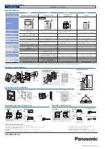
Specifications
VL-MVN511
VL-V555
VL-PS241
VL-RLY1
Model number and name
Main Monitor Station (Main monitor)
Door Station (Doorphone)
Power Supply Unit
* indoor use only
Relay Box
Dimensions
(mm)
Power source
Power supply unit (VL-PS241)
24 V DC, 0.5 A
Power supplied by the main monitor
Input: 220-240 V AC, 0.2 A ( 50 / 60 Hz )
Output: 24 V DC, 0.6 A
Power supplied by the main monitor
Power consumption
Standby: Approx. 1.8 W
During operation: Approx. 10 W
-
-
-
Dimensions (H x W x D)
(Excluding protruding sections)
186 x 161 x 23.5 mm
169 x 118 x 30 mm
104 x 100 x 54 mm
92 x 78 x 38 mm
Weight
485 g
395 g
215 g
130 g
Operating environment
Ambient temperature: Approx. 0 °C to +40 °C,
Relative humidity (non-condensing): up to 90 %
Ambient temperature: Approx. -15 °C to +55 °C,
Relative humidity (non-condensing): up to 90 %
(tested up to -20 °C)
Ambient temperature: Approx. 0 °C to +40 °C
Relative humidity (non-condensing): up to 90 %
Ambient temperature: Approx. 0 °C to +40 °C
Relative humidity (non-condensing): up to 90 %
Display
5-inch, wide colour / WQVGA (480 x 272 pixel)
-
-
-
Display Language
English
-
-
-
Talking method
Hands-free
-
-
-
Frequency range
Wi-Fi: (IEEE 802.11 b/g/n 2.4 GHz)
-
-
-
Viewing angle
-
Horizontally: Approx. 170°
Vertically: Approx. 130°
-
-
Installation method
Wall mount (mounting bracket supplied)
Surface mount (mounting base supplied)
* Optional flush mounting box is sold separately.
Wall mount or attach to DIN rail
Wall mount or attach to DIN rail
Minimum illuminance required
-
1 lx (within approx. 50 cm from the camera lens)
-
-
Lighting method
-
White coloured LED lights
-
-
IP rating / IK rating
-
IP54
*1
/ Compliant with IK07
-
-
External material
Flame retardant ABS and PS resin
Aluminium and flame retardant PC+PS resin
Flame retardant PC+ABS resin
Flame retardant ABS resin
*1 Water resistance is only assured if the Door Station is installed correctly according to the instructions in the Installation Guide, and appropriate water protection measures are taken.
Trademarks and registered trademarks
- Wi-Fi is a trademark or registered trademark of Wi-Fi Alliance.
- iPhone and iPad are trademarks of Apple Inc., registered in the U.S. and other countries.
- Android is a trademark of Google Inc.
- All other trademarks identified herein are the property of their respective owners.
Important
- Safety Precaution: carefully read the operating instructions and installation manual before using this product.
• The actual product may vary slightly from photograph.
• All pictures of the LCD display are simulated.
• Weights and dimensions are approximate.
• Design and Specifications are subject to change without notice.
• These products may be subject to export control regulations.
Installing the Doorphone
DISTRIBUTED BY :
MG-DHPL015EN 1510ITP/ZZZ-AZ1
Model Composition
VL-SVN511AZ
VL-MVN511 x 1, VL-V555 x 1
Screw x 2
Mounting base
(accessory)
Wire
(User supplied)
2mm Hex wrench
Screws (accessory) x 4
83.5 mm
Wall
Screws
Mounting
bracket
Wall
Wire (User supplied)
83.5 mm
Installing the Power Supply Unit
Installing the Relay Box
Front view
Front view
Top view
Bottom View
Top view
Bottom View
Side View
Top View
DC Cable
AC IN connector
To the electric lock
Remove the screw
on the cable cover.
25 mm
7 mm
R1 R2 R3
1 2
R1 R2 R3
1 2
1
2
S1 S2
S3 S4
DC OUT
terminal
Cable binder
hole
Electric lock
terminal
Main monitor
terminal connector
DC cable
binder hole
button
When using mounting box
(option): VL-MB554
Screws (accessory) x 4
169 mm
186 mm
118 mm
161 mm
Mounting
base
Mounting
bracket
Main Monitor
43.1 mm
86.8 mm
83.5 mm
83.5 mm
Image range
Centre of the
door station
1450 mm
2100 mm
2500 mm
400 mm
500 mm
130°
170°
500 mm
From the main monitor
Installing the Main Monitor
•Installation Position
9 mm
Cable from the main monitor
7 mm
25 mm
Cable from the electric lock
100 mm
151 mm
37 mm
AC cable
DC cable
Remove the screw
on the cable cover.
100
78
104
92
118
161
169
186
54
38
30
23.5
Up to 2


