3
1 Safety Precautions
1.1.
General Guidelines
1. When conducting repairs and servicing, do not attempt to modify the equipment, its parts or its materials.
2. When wiring units (with cables, flexible cables or lead wires) are supplied as repair parts and only one wire or some of the
wires have been broken or disconnected, do not attempt to repair or re-wire the units. Replace the entire wiring unit instead.
3. When conducting repairs and servicing, do not twist the Fasten connectors but plug them straight in or unplug them straight
out.
4. When servicing, observe the original lead dress. If a short circuit is found, replace all parts which have been overheated or
damaged by the short circuit.
5. After servicing, see to it that all the protective devices such as insulation barriers, insulation papers shields are properly
installed.
6. After servicing, make the following leakage current checks to prevent the customer from being exposed to shock hazards.
1.2.
Touch-Current Check
1. Plug the AC cord directly into the AC outlet. Do not use an isolation transformer for this check.
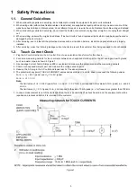
2. Connect a measuring network for touch currents between each exposed metallic part on the set and a good earth ground
such as a water pipe, as shown in Figure 1.
3. Use Leakage Current Tester (Simpson 228 or equivalent) to measure the potential across the measuring network.
4. Check each exposed metallic part, and measure the voltage at each point.
5. Reserve the AC plug in the AC outlet and repeat each of the above measure.
6. The potential at any point (TOUCH CURRENT) expressed as voltage U
1
and U
2
, does not exceed the following values:
For a. c.: U
1
= 35 V (peak) and U
2
= 0.35 V (peak);
For d. c.: U
1
= 1.0 V,
Note:
The limit value of U
2
= 0.35 V (peak) for a. c. and U
1
= 1.0 V for d. c. correspond to the values 0.7 mA (peak) a. c. and 2.0
mA d. c.
The limit value U
1
= 35 V (peak) for a. c. correspond to the value 70 mA (peak) a. c. for frequencies greater than 100 kHz.
7. In case a measurement is out of the limits specified, there is a possibility of a shock hazard, and the equipment should be
repaired and rechecked before it is returned to the customer.
Figure 1
Summary of Contents for Viera TX-P50VT50B
Page 25: ...25 7 4 No Picture ...
Page 38: ...38 ...
Page 44: ...44 ...
Page 46: ...46 12 3 Wiring 2 12 4 Wiring 3 ...
Page 47: ...Model No TX P50VT50B Y PR50VT50 Schematic Diagram Note S 1 ...
Page 48: ...Model No TX P50VT50B Y PR50VT50 Replacement Parts List Note S 2 ...
Page 49: ...Model No TX P50VT50B Y PR50VT50 A Board 1 14 S 3 ...
Page 50: ...Model No TX P50VT50B Y PR50VT50 A Board 2 14 S 4 ...
Page 51: ...Model No TX P50VT50B Y PR50VT50 A Board 3 14 S 5 ...
Page 52: ...Model No TX P50VT50B Y PR50VT50 A Board 4 14 S 6 ...
Page 53: ...Model No TX P50VT50B Y PR50VT50 A Board 5 14 S 7 ...
Page 54: ...Model No TX P50VT50B Y PR50VT50 A Board 6 14 S 8 ...
Page 55: ...Model No TX P50VT50B Y PR50VT50 A Board 7 14 S 9 ...
Page 56: ...Model No TX P50VT50B Y PR50VT50 A Board 8 14 and K Board S 10 ...
Page 57: ...Model No TX P50VT50B Y PR50VT50 A Board 9 14 S 11 ...
Page 58: ...Model No TX P50VT50B Y PR50VT50 A Board 10 14 S 12 ...
Page 59: ...Model No TX P50VT50B Y PR50VT50 A Board 11 14 S 13 ...
Page 60: ...Model No TX P50VT50B Y PR50VT50 A Board 12 14 S 14 ...
Page 61: ...Model No TX P50VT50B Y PR50VT50 A Board 13 14 S 15 ...
Page 62: ...Model No TX P50VT50B Y PR50VT50 A Board 14 14 S 16 ...
Page 63: ...Model No TX P50VT50B Y PR50VT50 C1 Board 1 2 S 17 ...
Page 64: ...Model No TX P50VT50B Y PR50VT50 C1 Board 2 2 S 18 ...
Page 65: ...Model No TX P50VT50B Y PR50VT50 C2 Board S 19 ...
Page 66: ...Model No TX P50VT50B Y PR50VT50 C3 Board S 20 ...
Page 67: ...Model No TX P50VT50B Y PR50VT50 SC Board 1 3 S 21 ...
Page 68: ...Model No TX P50VT50B Y PR50VT50 SC Board 2 3 S 22 ...
Page 69: ...Model No TX P50VT50B Y PR50VT50 SC Board 3 3 S 23 ...
Page 70: ...Model No TX P50VT50B Y PR50VT50 SS Board 1 2 S 24 ...
Page 71: ...Model No TX P50VT50B Y PR50VT50 SS Board 2 2 and SS2 Board S 25 ...
Page 72: ...Model No TX P50VT50B Y PR50VT50 A Board Foil side S 26 ...
Page 73: ...Model No TX P50VT50B Y PR50VT50 A Board Component side S 27 ...
Page 74: ...Model No TX P50VT50B Y PR50VT50 K Board S 28 ...
Page 75: ...Model No TX P50VT50B Y PR50VT50 C1 Board S 29 ...
Page 76: ...Model No TX P50VT50B Y PR50VT50 C2 Board S 30 ...
Page 77: ...Model No TX P50VT50B Y PR50VT50 C3 Board S 31 ...
Page 78: ...Model No TX P50VT50B Y PR50VT50 SC Board Foil side S 32 ...
Page 79: ...Model No TX P50VT50B Y PR50VT50 SC Board Component side S 33 ...
Page 80: ...Model No TX P50VT50B Y PR50VT50 SS Board Foil side S 34 ...
Page 81: ...Model No TX P50VT50B Y PR50VT50 SS Board Component side S 35 ...
Page 82: ...Model No TX P50VT50B Y PR50VT50 SS2 Board S 36 ...
Page 113: ...Model No TX P50VT50B Y PR50VT50 Exploded View 1 S 67 ...
Page 114: ...Model No TX P50VT50B Y PR50VT50 Exploded View 2 S 68 ...
Page 115: ...Model No TX P50VT50B Y PR50VT50 Packing 1 S 69 ...
Page 116: ...Model No TX P50VT50B Y PR50VT50 Packing 2 S 70 ...
Page 117: ...Model No TX P50VT50B Y PR50VT50 Packing 3 S 71 ...


