13 Schematic Diagram
13.1. Schematic Diagram Note
Notes:
1. Resistor
Unit of resistance is OHM [Q] (K=1,000, M =1,000,000).
2.
Capacitor
Unit of capacitance is |jF, unless otherwise noted.
3. Coil
Unit of inductance is H, unless otherwise noted.
4. Test Point
9
: Test Point position
5. Earth Symbol
j
I
t
: Chassis Earth (Cold)
^
: Line Earth (Hot)
6. Voltage Measurement
Voltage is measured by a DC voltmeter.
Conditions of the measurement are the following:
Power S o u rc e ........................................................AC220-240V, 50/60Hz
Receiving S ig n a l................................................... Colour Bar signal (RF)
All customer's c o n tro ls ......................................... Maximum positions
7. When arrow mark
( / )
is found, connection is easily found from the direction of arrow.
8. Indicates the major signal flow.
: Video ^
A u d io s
9. This schematic diagram is the latest at the time of printing and subject to change without
notice.
Summary of Contents for Viera TX-P42U20E
Page 21: ...7 4 No Picture 21 ...
Page 33: ...11 Block Diagram 11 1 Main Block Diagram 33 ...
Page 34: ...11 2 Block 1 4 Diagram 34 ...
Page 35: ...G 0 11 3 Block 2 4 Diagram I A I D IG IT A L S IG N A L P R O C E S S O R 35 ...
Page 36: ...11 4 Block 3 4 Diagram P P O W E R S U P P LY 36 ...
Page 38: ...38 ...
Page 40: ...12 3 Wiring 2 40 ...
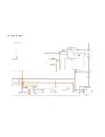
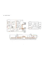
Page 43: ...13 2 P Board 1 4 Schematic Diagram A B C D E A P BO ARD LSEP1287BE HB 1 4 F 1 2 3 4 42 ...
Page 44: ...13 3 P Board 2 4 Schematic Diagram A P BO ARD LSEP1287BE HB 2 4 10 11 12 13 14 15 16 17 18 43 ...
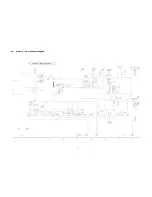
Page 45: ...13 4 P Board 3 4 Schematic Diagram A B C D E F 1 2 3 4 44 ф ф 5 ...
Page 46: ...13 5 P Board 4 4 Schematic Diagram 10 11 12 13 14 15 16 17 18 45 ...
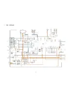
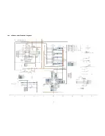
Page 47: ...13 6 A Board 1 19 Schematic Diagram A A A BO AR D 1 19 IIC B C D E F 1 2 3 4 9 46 ...
Page 52: ...13 11 А Board 6 19 Schematic Diagram A A BO AR D 6 19 STB MPU 46 47 48 49 ...
Page 54: ...13 12 А Board 7 19 Schematic Diagram A A BO AR D 7 1 9 HDMI 55 56 57 58 59 52 ...
Page 55: ...60 61 62 63 ...
Page 57: ...69 70 71 72 ...
Page 60: ...87 8 8 89 90 ...
Page 61: ...13 16 A Board 11 19 Schematic Diagram A A BO AR D 11 19 A V SW 91 92 93 94 95 96 97 98 99 56 ...
Page 63: ...FE_Virtual_M odule Peaks COMMON TO 3 19 Analog ASIC 104 105 106 107 108 57 ...
Page 68: ...140 141 142 143 144 61 ...
Page 71: ...63 ...
Page 72: ...13 24 A Board 19 19 Schematic Diagram A A BO AR D 19 19 DVB T C D EM O D U LATO R 64 ...
Page 75: ...13 27 C2 Board 1 2 Schematic Diagram A A C 2 BO AR D TN PA5095 1 2 ___ I TO A BOARD A32 B 67 ...
Page 78: ...13 30 SC Board 2 4 Schematic Diagram 10 I 11 1 12 1 13 1 14 1 15 1 16 1 17 1 18 70 ...
Page 79: ... 13 31 SC Board 3 4 Schematic Diagram 19 1 20 1 21 1 22 1 23 1 24 1 25 1 26 1 27 71 ...
Page 80: ...13 32 SC Board 4 4 Schematic Diagram 28 29 30 31 32 33 34 35 36 72 ...
Page 86: ...P BOARD COMPONENT SIDE LSEP1287BEHB B G 6 5 4 3 2 1 E F H 77 ...
Page 88: ...14 3 A Board 79 ...
Page 89: ...A BOARD COMPONENT SIDE A P42U20B A P42U20E A PR42U20 B G 6 5 4 3 2 1 E F H 80 ...
Page 92: ...14 6 SC Board SC BOARD FOIL SIDE TXNSC11DEK B G 6 5 4 3 2 1 E F H 83 ...
Page 93: ...SC BOARD COMPONENT SIDE TXNSC11DEK 6 5 4 3 2 1 A I b I C I d I E I F I G I H I I 84 ...
Page 94: ...14 7 SS Board SS BOARD FOIL SIDE TXNSS11DEK 6 5 4 3 2 1 A I b I C I d I E I F I G I H I I 85 ...
Page 95: ...SS BOARD COMPONENT SIDE TXNSS11DEK ...
Page 96: ......
Page 98: ...15 1 2 Exploded View 2 88 ...
Page 99: ...89 ...
Page 100: ...15 1 4 Packing 2 90 ...


