background image

FAQs, etc.

TV

28

29

Technical Information

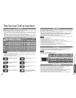
Input signal that can be displayed

 Mark: Applicable input signal for Component (Y, P

B

, P

R

), HDMI and PC (D-sub 15P)

Note

• 

Signals other than above may not be displayed properly.

• 

The above signals are reformatted for optimal viewing on your display.

Signal name

Horizontal

frequency (kHz)

Vertical

frequency (Hz)

Component

HDMI

PC

525 (480) / 60i

15.73

59.94

525 (480) / 60p

31.47

59.94

625 (576) / 50i

15.63

50.00

625 (576) / 50p

31.25

50.00

750 (720) / 60p

45.00

60.00

750 (720) / 50p

37.50

50.00

1,125 (1,080) / 60i

33.75

60.00

1,125 (1,080) / 50i

28.13

50.00

640 × 400 @70 Hz

31.46

70.07

640 × 480 @60 Hz

31.47

59.94

640 × 480 @75 Hz

37.50

75.00

800 × 600 @60 Hz

37.88

60.32

800 × 600 @75 Hz

46.88

75.00

800 × 600 @85 Hz

53.67

85.06

1,024 × 768 @60 Hz

48.36

60.00

1,024 × 768 @70 Hz

56.48

70.07

1,024 × 768 @75 Hz

60.02

75.03

1,024 × 768 @85 Hz

68.68

85.00

1,280 × 1,024 @60 Hz

63.98

60.02

Macintosh13” (640 × 480)

35.00

66.67

Macintosh16” (832 × 624)

49.72

74.54

Macintosh21” (1,152 × 870)

68.68

75.06

Frequently 

Asked Questions


Technical Information

FAQs

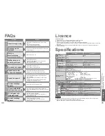
Before requesting service or assistance, please follow these simple guides to resolve the problem.

If problem still persists, please contact your local Panasonic dealer or Panasonic Customer Care Centre 

for assistance.

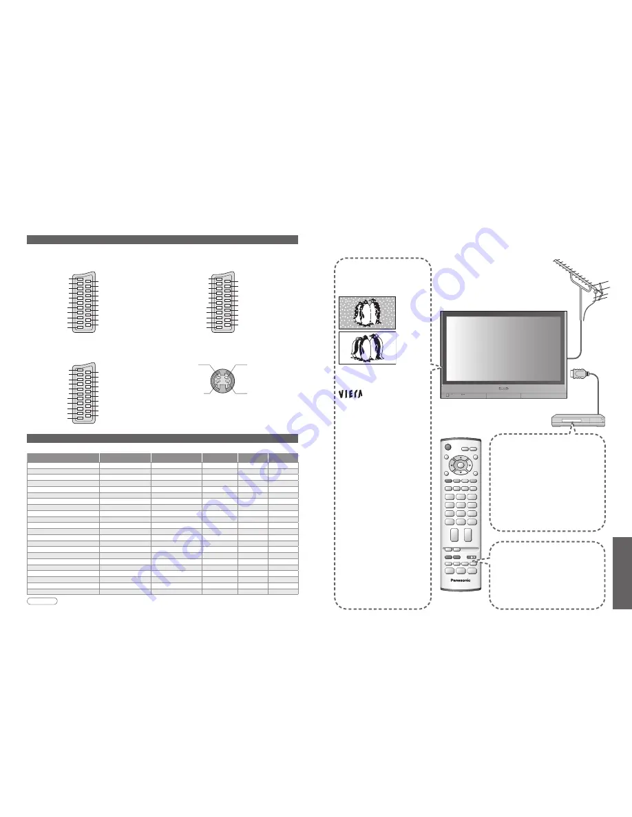
White spots or 

shadow images 

(noise)

• 

Check the position, direction, 

and connection of the aerial.

 logo appears 

at the four corners 

of the screen
Contrast is reduced

• 

The function to prevent after-image 

is activated. 

(Not a faulty symptom)

● The screen saver is activated if 

the TV unit is not operated for a 

certain time in AV mode.

● Contrast is lowered when 

teletext, radio, menu, etc. lasts 

for several minutes.

● "after-image" (p. 5)

Only one part 

remains dark

• 

A pixel or luminescent spot may 

occasionally be missing in plasma 

displays. 

(Not a faulty symptom)

Pictures from an 

equipment are unusual 

when the equipment is 

connected via HDMI

• 

Is the HDMI cable connected properly? 

(p. 24)

• 

Turn Off the TV unit and equipment, 

then turn them On again.

• 

Check an input signal from the equipment. 

(p. 28)

• 

Use an equipment compliant with 

EIA/CEA-861/861B.

The remote control 

does not work

• 

Are the batteries installed correctly? 

(p. 6)

• 

Has the TV unit been switched On?

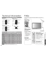
SCART and S-video terminal information

Socket Earth

CVBS out (video)

CVBS earth

Red in

Red earth

Green in

Green earth

Blue in

Blue earth

Audio out (L)

Audio out (R)

CVBS in (video)

RGB status earth

Status RGB

Earth

--

--

Status CVBS

Audio in (L)

Audio earth

Audio in (R)

21

19

17

15

13

11

9

7

5

3

1

20

18

16

14

12

10

8

6

4

2

■ 

AV1 

SCART terminal  

(RGB, VIDEO)

Suitable inputs for AV1 include RGB (Red / Green / Blue).

Socket Earth

CVBS out (video)

CVBS earth

S.C. - in

Earth

--

Earth

--

Earth

Audio out (L)

Audio out (R)

CVBS in (video)

Earth

--

Earth

--

Q-Link data

Status CVBS

Audio in (L)

Audio earth

Audio in (R)

21

19

17

15

13

11

9

7

5

3

1

20

18

16

14

12

10

8

6

4

2

■ 

AV2 

SCART terminal  

(VIDEO, S-VIDEO, Q-Link)

AV2 - Pins 15 and 20 are dependent on AV2 S-VHS / 

VIDEO switching.

Chrominance in

Socket Earth

CVBS out (video)

CVBS earth

Red in, S.C. - in

Red earth

Green in

Green earth

Blue in

Blue earth

Audio out (L)

Audio out (R)

CVBS in (video)

Earth

Status RGB

Earth

--

Q-Link data

Status CVBS

Audio in (L)

Audio earth

Audio in (R)

21

19

17

15

13

11

9

7

5

3

1

20

18

16

14

12

10

8

6

4

2

Luminance in

Chrominance earth

Luminance earth

■ 

AV4 

S-VIDEO 4 pin terminal

■ 

AV3 

SCART terminal  

(RGB, VIDEO, S-VIDEO, Q-Link)

AV3 - Pins 15 and 20 are dependent on AV3 S-VHS / 

VIDEO switching.

Summary of Contents for Viera TH-37PV60E

Page 1: ...ich could otherwise arise from inappropriate waste handling Please contact your local authority for further details of your nearest designated collection point Penalties may be applicable for incorrec...

Page 2: ...Warning Caution Notes 5 Maintenance 5 Be Sure to Read Advanced Features How to Use Menu Functions 14 picture sound quality etc Editing and Setting Channels 16 Displaying PC Screen on TV 19 External Eq...

Page 3: ...ove the TV with the lead plugged in the socket outlet Do not place a heavy object on the lead or place the lead near a high temperature object Do not twist the lead bend it excessively or stretch it D...

Page 4: ...by On Off switch in On position On Off switch Swing up the door at PULL C A T S Contrast Automatic Tracking System sensor senses brightness to adjust picture quality in Auto viewing mode p 14 Power la...

Page 5: ...g Q Link p 20 Watching TV To record TV programmes Auto Setup is now complete and your TV is ready for viewing You can now use the remote control to turn On the unit or turn the unit to standby mode Po...

Page 6: ...edure to view the input To connect the equipment p 24 Select the connector connected to the equipment AV1 AV2 S video AV3 S video AV4 S video Component PC VCR DVD VCR DVD switch Select VCR DVD Standby...

Page 7: ...Frequently viewed pages p 13 To change mode Teletext in Setup menu p 14 To adjust contrast MENU As the blue bar is displayed FULL TOP BOTTOM Reveal hidden data MENU red Re hide red Reveal hidden word...

Page 8: ...left speakers Balance Headphone volume Adjusts the volume of the headphones High Low Headphone volume MPX Select stereo monaural Mono Stereo Normally Stereo Stereo signal cannot be received Mono M1 M2...

Page 9: ...ble characters Select the Name eld Select the character To next character Repeat Select the programme number to edit Programme number Name Edit Programme edit Prog Chan Name Lock Sys 1 2 3 4 5 CH44 CH...

Page 10: ...correction Side panel Power save OSD language p 14 Sound menu p 14 Displaying PC Screen on TV Editing and Setting Channels Set automatically Auto setup Set manually Manual tuning Manual tuning 02 78...

Page 11: ...y the menu Enjoy additional HDMI Inter Operability with Panasonic products which have HDAVI Control function HDMI connections to some Panasonic equipments Panasonic DVD Recorder DIGA Panasonic Player...

Page 12: ...nect DVD player Playback Connect Set top box RGB input Connect VCR DVD recorder and Set top box example Connect DVD recorder and VCR example Easy playback For connection to HDMI2 terminal refer to p 2...

Page 13: ...ecorder To watch DVDs DVD player To watch camcorder images Video camera To watch satellite broadcasts Set top box To play games Game equipment Q Link Control with HDMI Recommended Connection SCART cab...

Page 14: ...frequency 59 to 86 Hz more than 1 024 signal lines could result in incorrect display of the image A PC adapter is not necessary for the DOS V compliant D sub 15 pin connector Note Some PC models cann...

Page 15: ...hen teletext radio menu etc lasts for several minutes after image p 5 Only one part remains dark A pixel or luminescent spot may occasionally be missing in plasma displays Not a faulty symptom Picture...

Page 16: ...1000 3 3 EN55020 EN55022 EN55024 TH 37PV60E TH 42PV60E Power Source AC 220 240 V 50 60 Hz Power Consumption Average use 241 W 261 W Standby condition 0 3 W Plasma Display panel Drive method AC type As...

Reviews: