background image

4

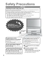
Safety Precautions

If you fi nd any
abnormality, remove 
the mains plug immediately!

(such as strange smell or smoke)

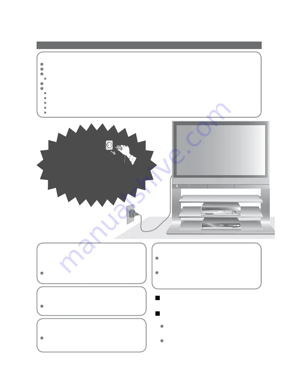
Keep liquids away from the TV

To prevent damage which may result in fi re or 
shock hazard, do not expose this appliance to 
dripping or splashing.
Do not place containers with water (fl ower vase, 
cups, cosmetics, etc.) above the set. (including on 
shelves above, etc.)

AC 220-240 V
50 / 60 Hz

Do not remove covers
NEVER modify the unit yourself

(High-voltage components may cause serious
electrical shock.)

Have the unit checked, adjusted, or repaired at 
your local Panasonic dealer.

Do not place foreign objects
inside the unit

Do not let metal or fl ammable objects drop into the unit 
through the air vents (fi re or electrical shock may result).

Using an unauthorized stand or other fi xtures may
make the unit shaky, risking injury. Be sure to ask 
your local Panasonic dealer to perform setup.
Use optional stands / mounts (p. 6).

Use only the dedicated stands / 

 mounting 

equipment

Handling the mains plug and lead

Insert the mains plug fully into the socket outlet. (If the mains plug is loose, it could generate heat and cause fi re.)
Ensure that the mains plug is easily accessible.
Ensure the grounding pin on the mains plug is securely connected to prevent electrical shock.

An apparatus with CLASS I construction shall be connected to a mains socket outlet with a protective earthing connection.

Do not touch the mains plug with a wet hand. (This may cause electrical shock.)
Do not damage the mains lead. (A damaged lead may cause fi re or electrical shock.)

Do not move the TV with the lead plugged in the socket outlet.
Do not place a heavy object on the lead or place the lead near a high-temperature object.
Do not twist the lead, bend it excessively, or stretch it.
Do not pull on the lead. Hold onto the mains plug body when disconnecting lead.
Do not use a damaged mains plug or socket outlet.

Warning

Do not place the TV on an unstable

 surface

Do not expose to direct sunlight 
and other sources of heat

Avoid exposing the TV set to direct sunlight and other 
sources of heat. To prevent fi re never place any type 
of candle or naked fl ame on top or near the TV set.

Summary of Contents for Viera TH-37PV45EH

Page 1: ...9 C 0 PROGRAMME DIRECT TV REC ASPECT MENU OK Operating Instructions Plasma Television English Please read these instructions before operating your set and retain them for future reference The images shown in this manual are for illustrative purposes only Model No TH 37PV45EH ...

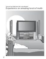
Page 2: ...2 Turn your own living room into a movie theatre Experience an amazing level of multi ...

Page 3: ...ure to Read Advanced Features How to Use Menu Functions 14 picture sound quality etc Editing and Setting Channels 16 Displaying PC Screen on TV 19 External Equipment 20 Q Link Control with HDMI Connections Basic Features Watching TV 10 Watching Videos and DVDs 11 Viewing Teletext 12 Enjoy your TV Technical Information 26 FAQs 29 Licence 31 Specifications 31 FAQs etc Accessories Options 6 Identifyin...

Page 4: ...ling the mains plug and lead Insert the mains plug fully into the socket outlet If the mains plug is loose it could generate heat and cause fire Ensure that the mains plug is easily accessible Ensure the grounding pin on the mains plug is securely connected to prevent electrical shock An apparatus with CLASS I construction shall be connected to a mains socket outlet with a protective earthing conne...

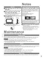
Page 5: ...Cabinet Mains plug Daily care Gently wipe the surface clean of dirt by using a soft cloth Major contamination Wipe the surface clean using a soft cloth dampened with clean water or water containing a small amount of neutral detergent Then using a soft dry cloth evenly wipe the surface clean until it is dry Daily care Wipe the surface clean using a soft dry cloth Major contamination Dampen a soft c...

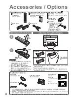
Page 6: ...an Guarantee Card Attaching the cable clampers Do not bundle the RF cable and mains lead together could cause distorted image Fix cables with clampers as necessary When using the optional accessory follow the option s assembly manual to fix cables Standard accessories Check that you have the accessories and items shown Remove from the TV unit Push both side hooks and pull out Ferrite core J0KF00000...

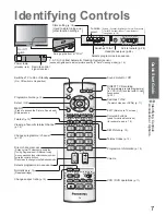
Page 7: ...programmes in sequence Direct channel access During normal TV viewing or when in the Tuning Programme edit or Manual tuning menus press and then enter channel number using the numeric buttons Press twice to change to the Cableband mode Changes programme channel p 10 Viewing a favourite teletext channel p 12 Teletext p 12 MENU Press to access the Picture Sound and Setup menus Select OK Programme Gu...

Page 8: ...V Mains lead Fastener To unfasten Connect to AV2 or AV3 for a unit supporting Q Link p 20 ŶWatching TV ŶTo record TV programmes Connect after all the other connections External equipments and cables shown in this manual are not supplied with this TV Please ensure that the unit is disconnected from the mains before attaching or disconnecting any leads ...

Page 9: ...ted by your local dealer Auto Setup is now complete and your TV is ready for viewing You can now use the remote control to turn On the unit or turn the unit to standby mode Power lamp On 2 If Q Link p 20 equipment is connected channel information is automatically downloaded to the equipment To edit channels Programme edit p 16 Auto Setup Connection Select your country select To set manually green ...

Page 10: ...econd watch down Display status information Display hide status information Displayed information Programme number Programme name Channel number MPX mode p 14 Sound system p 14 Aspect mode Change aspect ratio or 14 9 ASPECT Each press changes the mode Change the aspect ratio p 26 While the bar is displayed red green Auto aspect 16 9 14 9 Just 4 3 4 3 Full HD signal only Zoom1 Zoom2 Zoom3 Programme...

Page 11: ... equipment has an aspect adjustment function set to 16 9 For details see the manual of the equipment or ask your local dealer ŶTo return to TV TV AV example AV1 red PC blue yellow twice With the equipment turned On Select the external input green red yellow green yellow blue red Panasonic equipment connected to the TV can be directly operated with the remote control HDMI1 HDMI2 blue Displays the s...

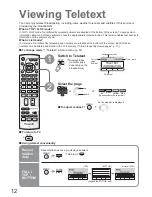
Page 12: ...e In TOP FLOF mode four differently coloured subjects are situated at the bottom of the screen To access more information about one of these subjects press the appropriately coloured button This facility enables fast access to information on the subjects shown What is List mode In List mode four differently coloured page numbers are situated at the bottom of the screen Each of these numbers can be...

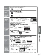
Page 13: ...yed The number changes to white Corresponding colour button ŶTo change stored pages VCR 1 2 3 4 5 6 7 8 9 0 OK hold down Enter new page number Colour button you want to change 0 0 0 Enter the 4 digit number example P6 Appears at upper left corner of the screen ŶTo view specific sub page MENU blue Sub pages The number of sub pages varies depending on the broadcasters up to 79 pages It may take some ...

Page 14: ... EXIT ŶTo return to the previous screen MENU Select the menu Select the item example Picture menu select select Adjust or select change example Picture menu example Picture menu Changed Number and positions of alternatives Moved Displays the next screen ŶChoose from among alternatives ŶAdjust using the slide bar ŶGo to the next screen ŶTo reset the setting N ŶMenu list next store Required by some ...

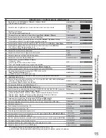
Page 15: ...ly HDMI1 input Auto Chooses the connector to which a Q Link compatible equipment is connected Off AV2 AV3 p 24 Q Link AV2 Chooses the signal to be transmitted from the TV to Q Link TV AV1 AV2 AV3 AV4 Monitor Monitor Image displayed on screen Component signals cannot be outputted AV2 out TV Control with HDMI function Off On p 21 Control with HDMI On Teletext display mode TOP FLOF List p 12 Teletext...

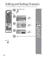
Page 16: ...m Volume correc Decoder AV2 Tuning menu Auto Access Off TV EXIT MENU OK MENU 16 Editing and Setting Channels Select Setup menu Select Tuning menu 3 1 2 Select the function 4 Display the menu 5 Set Edit channels ŶDelete ŶAdd ŶMove ŶChange channel number ŶChange name ŶLock ŶChange sound system ŶDownload to equipment Programme edit The current channel settings can be changed according to your needs a...

Page 17: ...ot select the channel with number buttons or the C button when locked Store Editing and Setting Channels Programme edit Prog Chan Name Lock Sys 1 2 3 4 5 CH44 CH51 CH41 CH47 CH37 ABC XYZ FTP 123 456 Off Off Off Off Off SC1 SC1 SC1 SC1 SC1 ŶTo change channel number Select the Chan field Change number Can also be changed with C and number buttons ŶTo download channel information to a Q Link compatibl...

Page 18: ...ark Sverige Norge Suomi Belgium Schweiz ELLADA Polska Česká republika Magyarország E Eu Country OK OK Start Auto setup set The settings are downloaded to a Q Link compatible equipment connected to the unit All previous settings are erased When the sequence is completed the broadcast of programme number 1 will appear Automatically set the channels received in the area Select your country Settings a...

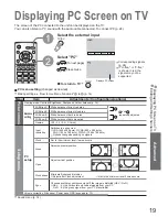
Page 19: ...d repeatedly adjusted W B High B White balance of bright blue area W B Low R White balance of dark red area W B Low B White balance of dark blue area Gamma 2 0 2 2 2 5 S Curve Setup menu PC setup Input resolution Switches to a wide view VGA 640 x 480 dots WVGA 852 x 480 dots XGA 1 024 x 768 dots WXGA 1 366 x 768 dots Options change depending on signals Clock Set to the minimum level if noise occur...

Page 20: ...logic or SMARTLINK Connect the equipment to this unit s AV2 or AV3 terminal via a fully wired SCART cable p 22 Q Link terminal setup in Setup menu Q Link AV2 AV3 out p 14 Q Link DIRECT TV REC DIRECT TV REC Direct TV Recording Recording the current programme in VCR DVD recorder immediately When Direct TV Recording is performed the recording equipment is automatically turned on if it is in Standby m...

Page 21: ...ut mode is returned Power on link When the connected Panasonic equipment is operated TV is also automatically turned on and the content is reproduced Only when TV is in Standby mode Power off link When TV is set to Standby mode the connected Panasonic equipment is also automatically set to Standby select Control with HDMI ControlTM Preparations For the first time When adding new equipment reconnect...

Page 22: ...ONENT AUDIO IN L R L R Y PB PR AV4 S V V L R L R PR PB Y R L V S V R L V S V 22 Connections ŶConnect VCR DVD recorder Recording Playback ŶConnect DVD player Playback ŶConnect Set top box RGB input Rear of the TV Rear of the TV Front of the TV Rear of the TV Front of the TV VCR DVD recorder DVD player Set top box External equipments and cables shown are not supplied with this TV or or or or or Conn...

Page 23: ...x example ŶConnect DVD recorder and VCR example ŶEasy playback For connection to HDMI2 terminal refer to p 24 Rear of the TV Rear of the TV Rear of the TV This TV Panasonic Player theatre Panasonic DVD recorder DIGA Panasonic Amplifier Panasonic DVD recorder DIGA Set top box VCR Speaker system SCART SCART SCART HDMI This TV Speaker system DVD recorder VCR DVD recorder SCART SCART SCART SCART HDMI Ŷ...

Page 24: ...order images Video camera To watch satellite broadcasts Set top box To play games Game equipment Q Link Control with HDMI Recommended Connection PC Viewing Listening Control with HDMI p 21 Types of connectable equipment to each connector Connections overview To listen with speakers DIGA or Panasonic Amplifier External Equipment Conversion adapter if necessary within 10 cm VIDEO or S VIDEO Headphone...

Page 25: ... RGB VIDEO S VIDEO S VIDEO COMPONENT AUDIO IN L R L R Y PB PR Set top box DVD Recorder VCR SCART cable RF cable or Q Link AV4 Y PB PR COMPONENT 1 2 SCART cable Q Link To watch satellite broadcasts To record playback To watch DVDs DVD player External Equipment SCART cable ...

Page 26: ...etects a widescreen signal it switches into the appropriate 16 9 or 14 9 widescreen mode If Auto aspect does not detect a widescreen signal then this advanced TV set enhances the picture for optimum viewing pleasure The text shown on the screen indicates how Auto aspect determined which ratio to use WIDE appears in the top left of the screen if a widescreen identification signal WSS is found or a s...

Page 27: ... and the equipment HDMI compatible equipment 1 with an HDMI or DVI output terminal such as a set top box or a DVD player can be connected to the HDMI terminal using an HDMI compliant fully wired cable Note HDMI2 terminal is for digital signal only Use with a PC is not assumed The 720p 1080i signals will be reformatted before being displayed on the screen If the connected equipment has an aspect ad...

Page 28: ...rmation Socket Earth CVBS out video CVBS earth Red in Red earth Green in Green earth Blue in Blue earth Audio out L Audio out R CVBS in video RGB status earth Status RGB Earth Status CVBS Audio in L Audio earth Audio in R 21 19 17 15 13 11 9 7 5 3 1 20 18 16 14 12 10 8 6 4 2 ŶAV1 SCART terminal RGB VIDEO Suitable inputs for AV1 include RGB Red Green Blue Socket Earth CVBS out video CVBS earth S C ...

Page 29: ...faulty symptom Ɣ The screen saver is activated if the TV unit is not operated for a certain time in AV mode Ɣ Contrast is lowered when radio menu etc lasts for several minutes Ɣ after image p 5 Only one part remains dark A pixel or luminescent spot may occasionally be missing in plasma displays Not a faulty symptom Pictures from an equipment are unusual when the equipment is connected via HDMI Is ...

Page 30: ...bout 30 min after broadcasting ends An error message appears Contact the authorized Service Centre Sound is unusual Set the sound setting of the connected equipment to 2ch L PCM Check the HDMI1 input setting in the Sound menu p 14 If digital sound connection has a problem select analogue sound connection p 27 Sound level is low or sound is distorted Sound signal reception may be deteriorated Set M...

Page 31: ... 5 mm Jack 1 PC signals VGA SVGA XGA SXGA compressed Horizontal scanning frequency 31 69 kHz Vertical scanning frequency 59 86 Hz Receiving Systems Band name PAL B G H I SECAM B G SECAM L L VHF E2 E12 VHF H1 H2 ITALY VHF A H ITALY UHF E21 E69 CATV S01 S05 CATV S1 S10 M1 M10 CATV S11 S20 U1 U10 CATV S21 S41 Hyperband PAL D K SECAM D K VHF R1 R2 VHF R3 R5 VHF R6 R12 UHF E21 E69 PAL 525 60 Playback o...

Page 32: ...ntact your local authority for further details of your nearest designated collection point Penalties may be applicable for incorrect disposal of this waste in accordance with national legislation For business users in the European Union If you wish to discard electrical and electronic equipment please contact your dealer or supplier for further information Information on Disposal in other Countrie...

Reviews: