Power On Operation
The power command from the power switch on the S board or the remote control receiver on the K board is
provided to the Main CPU on the A board (IC1100) thru connector A1. The CPU on the A board outputs the
“TV_SUB_ON” Command (3.2V) and the PANEL_STB_ON” command (3.2V).
The “TV_SUB_ON” command is provided to pin 6 of connector P7 of the power supply through pin 14 of
connector A6 of the A board to develop the F_STB+15V. At this time the relays on the power supply are
triggered and a “click” sound can be heard.
The F+15V from the P board is applied to several voltage regulator (IC5603, IC5401, and IC5607) on the A
board.
The voltage outputs from these ICs are called SUB5V, SUB9V, SUB3.3V, SUB1.8V, SUB1.3V, and BT30V.
They used by various circuits on the A board.
To avoid catastrophic failures, they are monitored by an SOS Detect circuit (IC5480) for over-voltage and
over-current conditions. This SOS Detect circuit is controlled by the TV_SUB_ON command from the Main
CPU (IC1100).
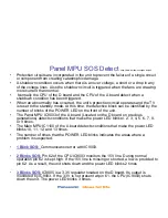
Any abnormalities of the SUB5V, SUB9V, or BT30V triggers the SOS circuit. The TV shuts down and the
power LED blinks 10 times.
The “PANEL_STB_ON” is used to turn on the 3.3V regulator (IC9004) on the A board. The output voltage is
applied to the “Panel” CPU on the A board (Formerly located in the D board).
The Panel CPU on the A board outputs the “PANEL_MAIN_ON” Command (3.2V) to pin 11 of connector
P25 on the P board.
The PANEL MAIN ON command turns on the power supply circuit that outputs the Vsus, Vda, 15V, and 5V.
https://www.werbemousepads.de/pdf/
Summary of Contents for Viera TC-P42S1
Page 12: ...VIErA Technology https www werbemousepads de pdf ...
Page 22: ...S Series Full HD https www werbemousepads de pdf ...
Page 23: ...Connectors Boards Location TC P42S1 https www werbemousepads de pdf ...
Page 25: ...Standby Operation https www werbemousepads de pdf ...
Page 27: ...Power On https www werbemousepads de pdf ...
Page 29: ...Sub Voltages https www werbemousepads de pdf ...
Page 33: ...SOS Blinking Timing Chart https www werbemousepads de pdf ...
Page 34: ...SOS Detect Block Diagram TC P42S1 https www werbemousepads de pdf ...
Page 35: ...Panel Drive SOS Detect Block Diagram TC P42S1 https www werbemousepads de pdf ...
Page 36: ...Panel Drive SOS Detect Block Diagram TC P42X1 https www werbemousepads de pdf ...
Page 46: ...6 Blinks Error Code TC P42X1 https www werbemousepads de pdf ...
Page 48: ...DRV RST Block Diagram TC P42S1 https www werbemousepads de pdf ...
Page 50: ...DRV RST Block Diagram TC P42X1 https www werbemousepads de pdf ...
Page 52: ...8 Blinks Error Code TC P42S1 https www werbemousepads de pdf ...
Page 56: ...11 Blinks Error Code https www werbemousepads de pdf ...
Page 62: ...SU SD Boards Isolation https www werbemousepads de pdf ...
Page 66: ...Signal Process Block https www werbemousepads de pdf ...
Page 67: ...Signal Process Block Diagram https www werbemousepads de pdf ...
Page 69: ...Service Notes https www werbemousepads de pdf ...
Page 72: ...Self Check Menu https www werbemousepads de pdf ...


