Panasonic Viera TC-58PS24 Operating Instructions Manual Download Page 7

6

7

Accessories

Assembly screws


A

 (for 

58”)

XYN5+F25FN

M5 × 25 (Silver) (4)

 (for 

65”)

THEL074

M5 × 30 (Silver) (6)

B

 (for 

58”)

THEL073N

M5 × 30 (Black) (4)


(for 

65”)

XYN6+F25FJK

M6 × 25 (Black) (4)

Poles (2)

(for 58”)

L

R


L

 or 

R

 is printed at the 

bottom of the poles.

(for 65”)

Front

Back

 Base (1)

(for 58”)

(for 65”)

Allen wrench 

(included tool only for 65”) 

C

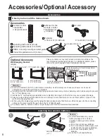
Accessories/Optional Accessory

Accessories

Remote Control 

Transmitter

 N2QAYB000485

Batteries for the

Remote Control

Transmitter (2)

 AA Battery

AC cord

Product Registration Card (U.S.A.)

Operating Instructions (Book)

VIERA Concierge and Quick start guide

Installing the remote’s batteries

Open

Hook

Note the correct polarity

(+ or -).

Close

Caution


Incorrect installation may cause 
battery leakage and corrosion, 
resulting in damage to the remote 
control.

 Do not mix old and new batteries.

 Do not mix different battery types (such 

as alkaline and manganese batteries).

 Do not use rechargeable (Ni-Cd) 

batteries.


Do not burn or break batteries.

Optional Accessory

Please contact your nearest Panasonic dealer to purchase the 
recommended wall-hanging bracket. For additional details, please 
refer to the wall-hanging bracket installation manual.

Wall-hanging bracket

(angle)

  TY-WK5P1RW (for 58”)


a:  19.7” (500 mm)

b: 11.8” (300 mm)

  TY-WK6P1RW (for 65”)


a:  26.9” (684 mm)

b: 11.8” (300 mm)

Rear of the TV

Holes for wall-hanging 

bracket installation

Screw for fixing the TV onto the wall-hanging bracket 

(not supplied with the TV)

Depth of screw:

minimum  0.59” (15.0 mm) (58”)

0.55” (14.0 mm) (65”)

maximum  1.18” (30.0 mm)

(View from the side)

a

b

M8

Warning

  In order to maintain the TV’s performance and safety, be absolutely sure to ask your dealer or a licenced 

contractor to secure the wall-hanging brackets.

  Carefully read the instructions accompanying optional accessories, and be absolutely sure to take steps to prevent 

the TV from tipping over.

  Handle the TV carefully during installation since subjecting it to impact or other forces may cause product damage.
  Take care when fixing wall brackets to the wall. Always ensure that there are no electrical cables or pipes in the 

wall before hanging bracket.

  When using the angled-type wall hanging bracket, please ensure that there is sufficient space for the connecting 

cables not to press against the wall when the TV is tilted forward.

  For safety reasons, remove units no longer being used from their wall-mounted locations.

Accessories

Check you have all the items shown.

M8

Operating Instructions (CD-ROM)

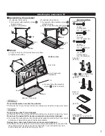
Attaching the pedestal to TV

Assembling the pedestal

[TC-58PS24 (TBLX0157)]

[TC-65PS24 (TBLX0195)]

  Fix securely with assembly screws 

A

.

(Total 4 screws)

  Tighten screws firmly.

  Fix securely with assembly screws 

A

.

(Total 6 screws)

  Tighten screws firmly using Allen wrench 

C

A

L

R

Pole

Front

Pole

Base

A

C

Pole

Front

Pole

Base

Set-up


  Carry out work on a horizontal and level surface.


  Tighten screws firmly.

(Image: TC-65PS24)

B


Fix securely with assembly 
screws 

B

. (Total 4 screws)

Rear side

Arrow 

mark

Pole

Hole for pedestal 

installation

Pole

 Base 

Bottom view

Warning

Do not disassemble or modify the pedestal.

  Otherwise the TV may fall over and become damaged, and personal injury may result.

Caution

Do not use any other TV and displays.

  Otherwise the TV may fall over and become damaged, and personal injury may result.

Do not use the pedestal if it becomes warped or physically damaged.


If you use the pedestal when it is physically damaged, personal injury may result. 
Contact your nearest Panasonic Dealer immediately.

During set-up, make sure that all screws are securely tightened.

  If sufficient care is not taken to ensure screws are properly tightened during assembly, 

the pedestal will not be strong enough to support the TV, and it might fall over and 

become damaged, and personal injury may result.

Pedestal

 TBLX0157 (TC-58PS24)

 TBLX0195 (TC-65PS24)

How to assemble (p. 7)

Summary of Contents for Viera TC-58PS24

Page 1: ...iciarse automáticamente En tal caso abra manualmente el archivo PDF en la carpeta MANUAL para visualizar las instrucciones TQB2AA0588 Gracias por su decisión de comprar este producto marca Panasonic Lea estas instrucciones antes de utilizar su televisor y guárdelas para consultarlas en el futuro Las imágenes mostradas en este manual tienen solamente fines ilustrativos Model No Número de modelo TC ...

Page 2: ...nal injury or even death if not installed correctly To prevent personal injury or death follow these warnings Install the Plasma TV in accordance with the manufacturer s recommended pedestal or stand corresponding hardware and installation instructions This Plasma TV is for use only with the following optional accessories Use with any other type of optional accessories may cause instability The fo...

Page 3: ...ct on the cord or place the cord near a high temperature object Do not twist the cord bend it excessively or stretch it Do not pull on the cord Hold onto the power plug body when disconnecting cord Do not use a damaged power plug or socket outlet If a problem occurs such as no picture or no sound or if smoke or an abnormal odor is detected from the Plasma TV unplug the power supply cord immediatel...

Page 4: ...me wall mounts are not designed to be mounted to walls with steel studs or old cinder block construction If you are unsure contact a professional installer A minimum of two people are required for installation Flat panel displays can be heavy Panasonic recommends that a qualified installer perform the wall mount installation See page 4 The American Academy of Pediatrics discourages television view...

Page 5: ...armful interference to radio or television reception which can be determined by turning the equipment off and on the user is encouraged to try to correct the interference by one or more of the following measures Reorient or relocate the receiving antenna Increase the separation between the equipment and receiver Connect the equipment into an outlet on a circuit different from that to which the rec...

Page 6: ...ng bracket installation Screw for fixing the TV onto the wall hanging bracket not supplied with the TV Depth of screw minimum 0 59 15 0 mm 58 0 55 14 0 mm 65 maximum 1 18 30 0 mm View from the side a b M8 Warning In order to maintain the TV s performance and safety be absolutely sure to ask your dealer or a licenced contractor to secure the wall hanging brackets Carefully read the instructions acc...

Page 7: ...rmly Image TC 65PS24 B Fix securely with assembly screws B Total 4 screws Rear side Arrow mark Pole Hole for pedestal installation Pole Base Bottom view Warning Do not disassemble or modify the pedestal Otherwise the TV may fall over and become damaged and personal injury may result Caution Do not use any other TV and displays Otherwise the TV may fall over and become damaged and personal injury m...

Page 8: ...8 Accessories Optional Accessory Continued AC cord connection To attach To remove Insert it firmly until the tabs on both sides click into place Keep pushing both sides until they snap and pull ...

Page 9: ... Committee Conventional broadcasting ATSC Advanced Television Systems Committee Digital TV Standards include digital high definition television HDTV standard definition television SDTV data broadcasting multi channel surround sound audio and interactive television AC Cord Connect after all the other connections have been made Back of the TV Cable TV AC 120 V 60 Hz VHF UHF Antenna or Cable You need...

Page 10: ...erminals will enable you to enjoy high definition digital images and high quality sound The HDMI connection is required for a 1080p signal To use COMPONENT terminals L R Y PB PR AUDIO OUT COMPONENT VIDEO OUT white red green blue red white red green blue red white red green blue red e g Blu ray Disc player AV Equipment To use COMPOSITE terminals L R COMPOSITE OUT yellow white red yellow white red y...

Page 11: ... down Displays or removes the channel banner Operates the Favorite channel list function Numeric keypad to select any channel or press to enter alphanumeric input in menus Use for digital channels Identifying Controls Note The TV consumes a small amount of electric energy even when turned off Do not place any objects between the TV remote control sensor and remote control TV controls indicators Ch...

Page 12: ... picture mode will regularly reset to Vivid and a Picture Refresh message will be displayed on the screen Yes select OK Select No and return to previous screen If you select Yes Screen enters the store demonstration mode To display the Set viewing mode screen again as shown above and select Home Use do one of the following Press and hold down the front POWER button for at least five seconds Unplug...

Page 13: ...tart Skip OK RETURN Select select OK Skip Go to Label inputs Start scanning the channels Available channels are automatically set Auto program Progress Number of analog channels Number of digital channels Press RETURN to quit 8 10 0 RETURN Complete the Auto program setup Completion message is displayed when the Auto program scan is successfully completed Auto program Auto program completed Press O...

Page 14: ...tart Skip OK RETURN Select select OK Skip Go to Label inputs Start scanning the channels Available channels are automatically set Auto program Progress Number of analog channels Number of digital channels Press RETURN to quit 8 10 0 RETURN Complete the Auto program setup Completion message is displayed when the Auto program scan is successfully completed Auto program Auto program completed Press O...

Page 15: ...C Delete abc R G B Y 1 4 GHI 7PQRS 2 ABC 5 JKL 8 TUV 3 DEF 6MNO 9WXYZ 0 LAST Blu r Video 2 NEXT GA GA Follow the instructions on screen to complete the following operations Label BLANK Not used Blu ray DVD DVD REC HOME THTR GAME COMPUTER VCR CABLE SATELLITE DVR CAMERA MONITOR AUX RECEIVER MEDIA CTR MEDIA EXT OTHER Adjust the Clock Set clock Select NEXT then press OK to go to the next step Step 6 o...

Page 16: ...nent 1 Component 2 Video 1 Video 2 PC HDMI 2 HDMI 3 HDMI 1 Menu structure Menu bar Press OK to move to the Menu items Menu items Press OK to proceed to next screen if available Help information Operation guide example Input labels Select the menu Custom Menu 0 0 Picture 1 2 Brightness Picture mode Contrast Reset to defaults select next Select the item Custom Menu Resets all picture adjustments to ...

Page 17: ...s vertical alignment and size when aspect setting is ZOOM PC adjustments Set PC display Advanced picture 3D Y C filter Minimizes noise and cross color in the picture Off On Color matrix Selects image resolution of component connected devices SD HD SD Standard Definition HD High Definition Only used with 480p video signal MPEG NR Reduces noise of specific digital signals of DVD STB etc Off On Black...

Page 18: ... off Note Not in use when Auto power on On Off Timer or Lock is set or while SD mode or Digital Channel is selected No signal for 10 minutes was activated will be displayed for about 10 seconds when the TV is turned on for the first time after the power was turned off by No signal for 10 minutes The on screen display will flash 3 2 and 1 to indicate the last three 3 remaining minutes prior to the ...

Page 19: ...for digital channels Check Signal meter If the signal is weak check the antenna and consult your local dealer The remote control does not work Are the batteries installed correctly Are the batteries new Pictures from external equipment are distorted when the unit is connected via HDMI Is the HDMI cable connected properly Turn Off the TV unit and equipment then turn them On again Check an input sig...

Page 20: ...ed technology through an intricate process Sometimes a few pixels may be bright or dark These pixels do not indicate a defective panel and will have no impact on the performance of the TV Check nearby electrical products car or motorcycle ignition systems fluorescent lamp etc Check Picture menu Check the cable connections Check that the correct input has been selected Check the channel settings Ch...

Page 21: ...rials or workmanship and DOES NOT COVER normal wear and tear or cosmetic damage nor does it cover markings or retained images on the glass panel resulting from viewing fixed images including among other things non expanded standard 4 3 pictures on wide screen TV s or onscreen data in a stationary and fixed location The Limited Warranty ALSO DOES NOT COVER damages which occurred in shipment or fail...

Page 22: ...iday 9 am 9 pm Saturday Sunday 10 am 7 pm EST For hearing or speech impaired TTY users TTY 1 877 833 8855 Accessory Purchases United States and Puerto Rico Purchase Parts Accessories and Instruction Books on line for all Panasonic Products by visiting our Web Site at http www pstc panasonic com or send your request by E mail to npcparts us panasonic com You may also contact us directly at 1 800 33...

Page 23: ...The warranty ALSO DOES NOT COVER damages which occurred in shipment or failures which are caused by products not supplied by Panasonic Canada Inc or failures which result from accidents misuse abuse neglect mishandling misapplication alteration faulty installation set up adjustments misadjustment of consumer controls improper maintenance power line surge lightning damage modification introduction ...

Page 24: ...espacio provisto a continuación y guardar este manual más el recibo de su compra como prueba permanente de su adquisición para que le sirva de ayuda al identificarlo en el caso de que le sea sustraído o lo pierda y también para disponer de los servicios que le ofrece la garantía Modelo Número de serie Panasonic Consumer Electronics Company Division of Panasonic Corporation of North America One Pan...

Reviews: