


8 Disassembly and Assembly Instructions
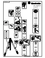
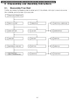
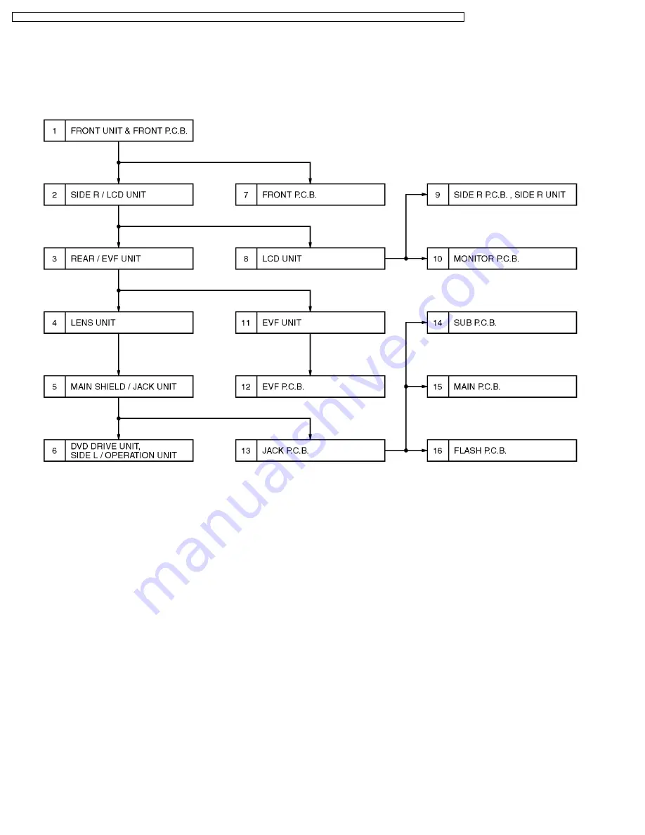
8.1. Disassembly Frow Chart
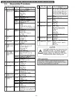
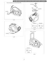
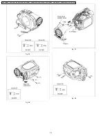
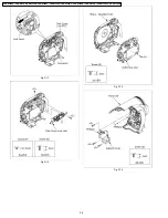
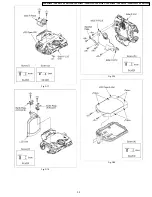
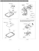
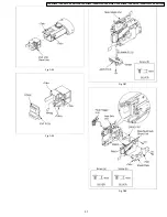
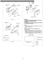
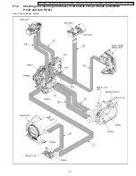
This flow chart indicates the disassembly steps the cabinet parts, P.C.B. and Mecha. Unit in order to access to be serviced.
When reinstalling, perform the steps in the reverse order.
28
VDR-D300EG / VDR-D300E / VDR-D300EB / VDR-D300EP / VDR-D300EE / VDR-D300GC / VDR-D300GN / VDR-D300SG / VDR-D300GCS / VDR-D308GK