– 67 –
Chapter 5 Operation — Control panel operation
f
Level meter display
Displays the level represented by 19 bars. (2 dB increments)
f
Standard level bar
At the
−
18 dB position or the
−
20 dB position
The setting in [MENU]
→
[AUDIO SETTINGS]
→
[AUDIO LEVEL]
→
[HEADROOM] will be the standard.
6 Warning/error displays
: Warning (details are displayed on the time code display in the following cases)
f
[SYSTEM ERROR !]
f
[TURN POWER OFF !]
f
[REC WARING !]
f
[CARD ERROR !] (when recording has stopped)
f
[TEMPORARY PAUSE]
: Alert
7 Time code display
f
[TCG 12:59:59:20]: Displays the time code generator value.
f
[UBG AB CD EF 98]: Displays the user bits generator value.
f
[Dur.00:59:59:23]: Displays the duration.
8 CAM INDEX/REEL number recording method display
f
F: Recorded as file name.
f
M: Recorded in metadata as [TYPE3] of [USER CLIP NAME].
9 CAM INDEX/REEL number
Displays the CAM INDEX, REEL number, and clip number.
10 Lock display/network status display
Displayed when button operations are disabled due to the <LOCK> switch.
The <REC> button is enabled even while lock is active.
When using the wired LAN
f
(No display): No compatible device.
f
(White): Operating but not connected.
f
(Yellow): Operating. A device is connected.
f
(Red): An error has occurred.
When using wireless LAN
f
(Gray): No compatible device.
f
(White): Operating but not connected.
f
(Yellow): Operating. A device is connected.
f
(Red): An error has occurred.
When using 4G/LTE (the status of the bar to display changes by the signal status)
f
(Gray): No compatible device.
f
(White): Operating but not connected.
f
(Yellow): Operating. A device is connected.
f
(Red): An error has occurred.
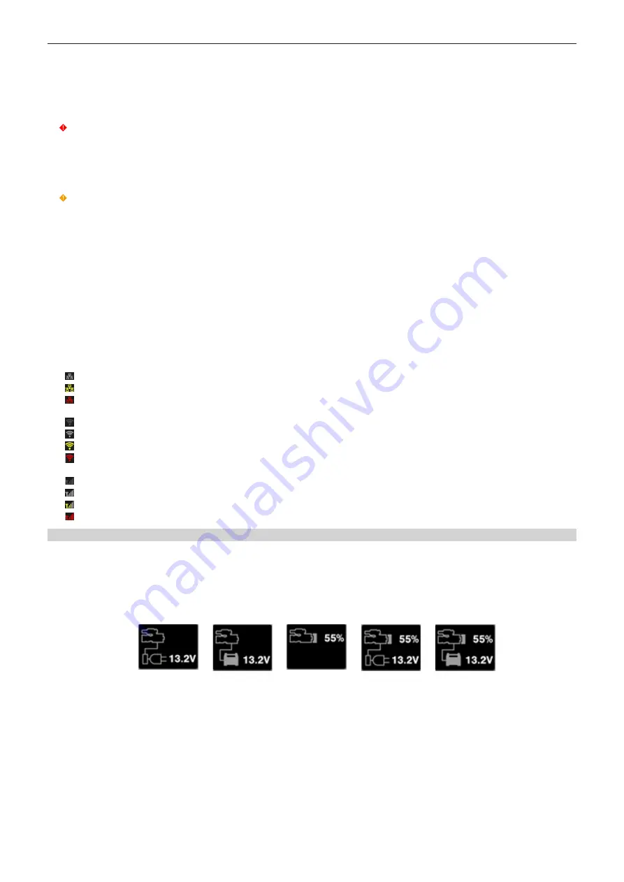
Power supply display
Displays the connection status and remaining capacity of the battery and external power supply.
The remaining capacity information is displayed in “%” if there is any. It is displayed as voltage “V” if % display is not possible.
Displays [EMP] in red character when the end is reached, and [LOW] in yellow character when the near end is reached.
Select [DC POWER SUPPLY] or [BATTERY] to match the power supply to connect in [MENU]
→
[SYSTEM SETTINGS]
→
[POWER MANAGEMENT]
→
[DC IN SOURCE] when connecting an external power supply to the <DC IN> terminal.
1
2
3
4
5
1 <DC IN> power supply display
This is the display when an AC adaptor ([DC POWER SUPPLY]) is connected to the <DC IN> terminal.
2 <DC IN> power supply display
This is the display when a battery is connected to the <DC IN> terminal.
3 Battery display
This is the display when a battery is connected to the battery holder.
4 Battery and <DC IN> power supply display
This is the display when a battery is connected to the battery holder and an AC adaptor ([DC POWER SUPPLY]) is connected to the <DC IN>
terminal.
5 Battery and <DC IN> power supply display
This is the display when a battery is connected to the battery holder and a battery is connected to the <DC IN> terminal.
Summary of Contents for VARICAM LT
Page 1: ...LT Operating Guide Version 1 W0316HM0 YI VQT5M58A E The photograph is an example of a system ...
Page 5: ...Before using the camera read this chapter Chapter 1 Overview ...
Page 91: ...This chapter describes video output Chapter 8 Output and Screen Display ...
Page 175: ...This chapter describes the specifications of this product Chapter 13 Specification ...
Page 182: ...Web Site http www panasonic com Panasonic Corporation 2016 ...


