223
UF-5500 / 4500
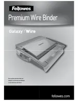
12.7. Remove Fuser Unit
2 leads for high valtage
Fig-01
Fuser Cover
(A)-a
Fuser Cover and Fuser Unit
(1) Remove the bottom plate.
(2) Remove the 2 leads for high voltage
and 1 connector for the sensor. (Fig-01)
(3) Remove the 3 screws (A)-a.
(4) Remove the Fuser Cover.
(5) Remove the 2 screws (G).
(6) Remove the Fuser Unit.
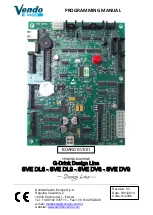
B1
(G)
Fig-01
Bottom view
Fuser Unit
2 leads for high valtage
Lead/Thermistor
Bottom View
Summary of Contents for UF-4500
Page 180: ...180 UF 5500 4500 ...
Page 248: ...248 UF 5500 4500 13 5 Test Chart 13 5 1 ITU T No 1 Test Chart ...
Page 249: ...249 UF 5500 4500 13 5 2 ITU T No 2 Test Chart ...
Page 281: ...281 UF 5500 4500 10 10 11 15 12 17 18 19 20 21 22 23 24 28 29 30 27 25 26 21 13 14 16 30 ...
Page 287: ...287 UF 5500 4500 130 131 132 133 134 135 136 137 138 139 140 141 PCB2 A UF 5500 only CN1 ...
Page 297: ...297 UF 5500 4500 ...
Page 305: ...305 UF 5500 4500 ...
Page 311: ...311 UF 5500 4500 501 502 503 504 506 507 505 508 509 511 510 514 513 512 P51 P53 P54 A51 P52 ...
Page 362: ...362 UF 5500 4500 ...