background image

7

English

1

2

3
4

6

7

9

10 11 12

5

8

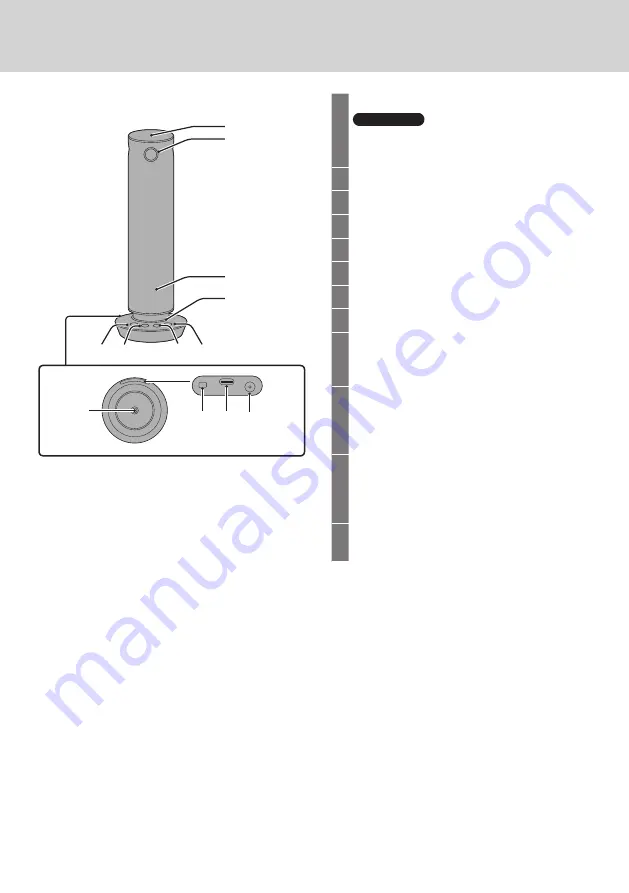
Part Names

1

Microphone

Attention

 •Do not block the microphone hole as this 

may cause a reduction in performance.

2

Cameras (4 facing 4 directions)

3

Speaker

4

Indicator

5

Audio muting button

6

Speaker volume [

] button

7

Speaker volume [

] button

8

[Mode] button

9

Camera mounting screw hole (screw: 

1/4-20UNC)

Used when mounting on a tripod, etc.

10

Security slot

You can connect a security cable that is 

compatible with Noble Wedge slots with 

mounting surfaces of 11 mm ɸ or less.

11

USB-C terminal

Outputs video and audio to the PC. It also 

receives power supplied from the Type-C 

interface of the Listed PC (5 V/3 A).

12

Power input terminal

Connect the AC adaptor.


On the 360 degree camera speakerphone

Summary of Contents for TY-CSP1

Page 1: ...e For business use Model No TY CSP1 English Thank you for purchasing the Panasonic product Please read these instructions before operating this product and retain them for future reference Be sure to read Safety Precautions page 2 to 3 before use W0722GU0 FJ DPQP1427ZA X1 ...

Page 2: ...umulating Failure to do so may cause a fire or electric shock due to moisture Remove the power plug and wipe it with dry cloth Do not insert or remove the power plug with wet hand Doing so may cause an electric shock Do not use the outlet or wiring devices exceeding rated values or with currents other than 100 240 V AC Using them exceeding rated values by connecting too many plugs in one outlet ma...

Page 3: ...oduct CAUTION Do not place the product at a high temperature location humid or dusty location or location subject to oil smoke or steam such as a cooking table and humidifier Doing so may cause a fire or electric shock Do not drop the product or expose it to strong impacts Doing so may cause injury or fire When the product has been mounted on a tripod do not move by holding this product The mounti...

Page 4: ...ot leave it lying around but be absolutely sure to dispose of it properly Do not touch the optical system parts Under no circumstances must they be touched In the unlikely event that they have become dusty remove the dust by using a camera blower or by wiping them gently with a lens cleaning paper Do not point the camera at strong lights When parts of the MOS sensor are exposed to spotlights or ot...

Page 5: ... using alcohol Soak a small amount of alcohol at a concentration of 60 or less in a soft cloth and wipe the housing Then be sure to use a dry cloth to wipe it Note that wiping the housing with a hard cloth or rubbing it strongly may cause damage Also do not allow water droplets to enter the inside to prevent malfunction Do not directly spray alcohol Do not use antiseptic solutions other than alcoh...

Page 6: ... in an appropriate manner and keep them away from young children The part numbers of accessories are subject to change without notice The actual part number may differ from the ones shown above In case you lost accessories please purchase them from your dealer Available from the customer service Dispose the packaging materials appropriately after taking out the items Note This product and the cabl...

Page 7: ...volume button 8 Mode button 9 Camera mounting screw hole screw 1 4 20UNC Used when mounting on a tripod etc 10 Security slot You can connect a security cable that is compatible with Noble Wedge slots with mounting surfaces of 11 mm ɸ or less 11 USB C terminal Outputs video and audio to the PC It also receives power supplied from the Type C interface of the Listed PC 5 V 3 A 12 Power input terminal...

Page 8: ...supplying 5 V 3 A power Only the supplied USB Type C to USB Type C cable can be used USB Type C to USB Type C cable Note When using only the USB Type C to USB Type C cable volume output is limited compared to when the AC adaptor is used When other connections are used Use the AC adaptor to supply power Get the AC adaptor ready Use by inserting the conversion plug into the supplied AC adaptor Use t...

Page 9: ...nput terminal on this product then plug the AC adaptor into the outlet Connect the PC to this product using the supplied USB cable USB Type C to USB Type C cable or USB Type C to USB Type A cable AC adaptor DC plug Note USB Type C is labeled as USB C on the main unit 2 Start the online meeting application or camera application on your PC to show the video and play the audio from this product For d...

Page 10: ...SB C terminal 3 Use the test feature of the application if there is one to run a test of the product s operations 4 Start using the application after you have completed the test If the functions did not work properly when tested If the camera images are not output see whether the camera muting function of the application is off If sound is not output from the speaker check whether the speaker volu...

Page 11: ...lume Lowers the volume Raises the volume This works in conjunction with the volume adjusting features of some operating systems and online meeting applications Changing the mode for displaying video Press or press and hold to switch the video mode page 12 Note The sound of the button press is linked to the volume of the speaker of the main unit Operations with the buttons on the main unit ...

Page 12: ... the bottom of the screen Single View Use when you want to show the face of the speaker at the maximum when conducting online meetings etc even if each screen is small The view of the person currently speaking takes up the entire screen When another person joins the conversation the screen switches to show that speaker Multi View Use when you want to enlarge the faces of the participants The focus...

Page 13: ...or the atmosphere of the entire meeting room There is no switching of the screens when people move or talk so the entire 360 degree view is shown constantly Stable View Use when you want to use the product as a web camera with a fixed position The video from only one of the four camera screens is displayed The video from the camera on the side with the buttons on this product is displayed ...

Page 14: ...n you press and hold the Mode button for 3 seconds or more the mode transitions to the Stable View Press the Mode button to cancel the Stable View Pressing the Mode button to switch modes Dual View Single View Multi View Surround View Stable View Pressing and holding the Mode button for 3 seconds or more Pressing the Mode button Video display modes Continued ...

Page 15: ...es in 10 seconds Device error Red LED blinks rapidly Blinks about 20 times in 10 seconds Normal circumstances camera and microphone on Green LED Camera off White LED Microphone is muted Red LED Camera off and microphone is muted Red LED circulates The gradation of the green LED changes only in the direction of the speaker s voice This may not work in some modes ...

Page 16: ...Mount the product on a tripod using the screw hole in the base of the product Place the tripod on a flat horizontal location Turn the screw to securely fix the tripod to this product Use a tripod that has a screw that meets the following specifications Screw for mounting tripod 1 4 20UNC 3 5 mm to 4 5 mm Attention Do not install the unit where people will be passing back and forth When using the u...

Page 17: ...ng firmware of the main unit Note The PC application is supported on the Microsoft Windows Windows 10 Windows 11 and macOS operating systems Getting the installer 1 When you connect the product to a PC PressIT360 appears in the list of devices and drives 2 When you open the PressIT360 drive the installer is saved to your PC 3 By running the installer the PC application is installed on your PC Note...

Page 18: ... Out Zooms out the camera images Adjusts the camera images vertically and horizontally Trigger Framing Switch Changes the image display mode Note Adjustment of the camera images and the zoom in and zoom out features work only on the camera image screen of this application Adjustment of the camera images occurs only within the area being taken by the camera and the area itself cannot be moved ...

Page 19: ...s the image frequency Setting values 50Hz 60Hz Noise Suppression Value Sets the noise reduction value Setting range 0 to 10 Echo Cancellation Sets echo reduction Setting values OFF ON Keyboard Noise Suppression Sets keyboard sound reduction Setting values OFF ON Factory Default Factory Default button All setting values are initialized Save Save button Saves the setting values to the device Cancel ...

Page 20: ...rial number of the connected device Test Speakerphone Tests operation of the speaker FW Update Updates the firmware on the device page 21 Troubleshooting Use this feature when a problem occurs Use only when directed by the dealer or manufacturer This is not a feature for performing recovery when a problem occurs PressIT360 application Continued ...

Page 21: ... Download the most recent firmware file and the installer for the PressIT360 application from the website for the product 2 Install the PressIT360 application onto your PC 3 Connect this product to the PC Connect both the DC cable and the USB cable 4 Run the PressIT360 application and select Diagnostic Utility FW Update 5 Select Manual Update and select the firmware file you downloaded in Step 1 U...

Page 22: ...e quality setting values All image quality setting values are initialized Press and hold all 4 buttons for 5 seconds or more 1 Press and hold the and buttons simultaneously for 5 seconds or more The LED blinks red 2 Press the button Note While the LED is blinking red if you press any button other than the button or allow 30 seconds or more to elapse the normal state is restored ...

Page 23: ...vity 35 dBFS S N ratio 68 75 dBA USB audio formats UAC 1 0 PCM 16 bit Speaker output 1 5 W When supplying power from USB Type C or 3 W When AC adaptor is connected Connection terminals USB Type C Receptacle USB2 0 DC plug 12 V 2 A Power supply USB Type C 5 V 3 A or AC adaptor DC 12 V 2 A Power consumption when outputting video 11 W Dimensions Φ H Φ64 mm 285 mm Φ2 52ʺ 11 23ʺ Operation base Φ100 mm ...

Page 24: ...eration from the Web setting screen of this product At least three 3 years from delivery of this product Panasonic Connect Co Ltd will give to any third party who contacts us at the contact information provided below for a charge no more than our cost of physically performing source code distribution a complete machine readable copy of the corresponding source code covered under GPL V2 0 LGPL V2 0...

Page 25: ...tween the equipment and receiver Connect the equipment into an outlet on a circuit different from that to which the receiver is connected Consult the dealer or an experienced technician for help FCC CAUTION To assure continued compliance follow the attached installation instructions and use only the provided power supply cord Any changes or modifications not expressly approved by Panasonic Corp of...

Page 26: ...onic Testing Centre Winsbergring 15 22525 Hamburg Germany Importer for UK Panasonic Connect UK a branch of Panasonic Connect Europe GmbH Maxis 2 Western Road Bracknell Berkshire RG12 1RT 4 1 62 Minoshima Hakata ku Fukuoka 812 8531 Japan Web Site https panasonic net cns prodisplays Panasonic Connect Co Ltd 2022 Panasonic Connect Co Ltd English Disposal of Old Equipment Only for European Union and c...

Reviews: