14.2.
Electrical Replacement Parts List
14.2.1. Replacement Parts List Notes
RTL (Retention Time Limited)
Note:
The marking (RTL) indicates that the Retention Time is Limited for this item.
After the discontinuation of this assembly in production, the item will continue to be avail
able for a specific period of time. The retention period of availability is dependant on the
type of assembly, and in accordance with the laws governing part and product retention.
After the end of this period, the assembly will no longer be available.
Abbreviation of part name and description
1. Resistor
2. Capacitor
Example:
Example:
ERD25TJ104
С ЮОКОНМ, J, 1/4W
ECKF1H103ZF
С
0.01UF, Z, 50V
Type
Allowance
Type
Allowance
Type
Allowance
С : Carbon
F : ±1%
F : Fuse
G : ±2%
M : Metal Oxide
J : ±5%
Metal Film
К : ±10%
S : Solid
M : ±20%
W : Wire Wound
Type
Allowance
С : Ceramic
С
±0.25pF
E : Electrolytic
D
±0.5pF
P : Polyester
F
±1 pF
Polyprop
G
±3pF
lene
J
±5pF
T : Tantalum
К
±10pF
L
±15pF
M
±20pF
P
+100%, -0%
Z
+80%, -20%
98
Summary of Contents for TX-PR42U10
Page 16: ...6 4 No Picture No Picture Check NG 16 ...
Page 28: ...9 1 4 Adjustment Volume Location 9 1 5 VR16600 Vad VR16841 Vscn Test Point Location 28 ...
Page 33: ...10 Block Diagram 10 1 Main Block Diagram 33 ...
Page 34: ...10 2 Block 1 4 Diagram JK8302 SPEAKER L SPEAKER R SD CARD SLOT 34 ...
Page 35: ...10 3 Block 2 4 Diagram FOR FACTORY USE FOR FACTORY USE I RM2501 I REMOTE 35 ...
Page 36: ...10 4 Block 3 4 Diagram ...
Page 38: ...38 ...
Page 40: ...11 3 Wiring 2 WIRE No 1 2 3 4 5 6 7 8 9 10 S1 P34 0 0 0 A8 FAN 0 0 0 0 0 0 0 40 ...
Page 41: ...11 4 Wiring 3 41 ...
Page 42: ...42 ...
Page 45: ...12 2 P Board 1 2 Schematic Diagram A B C D E F 1 2 3 4 5 6 7 44 ...
Page 46: ...12 3 P Board 2 2 Schematic Diagram 45 ...
Page 48: ...46 ...
Page 50: ...12 6 A Board 2 20 Schematic Diagram 10 11 12 13 14 15 16 17 18 48 ...
Page 51: ...12 7 A Board 3 20 Schematic Diagram NOT USE 19 20 21 22 23 24 25 26 27 49 ...
Page 52: ...0 12 8 A Board 4 20 Schematic Diagram NOT USE 36 28 29 30 31 32 33 34 35 50 ...
Page 53: ...12 9 A Board 5 20 Schematic Diagram 37 38 39 40 ...
Page 54: ...Ешшшшштшга J 41 42 43 44 45 51 ...
Page 57: ...12 12 A Board 8 20 Schematic Diagram A A B O A R D 8 20 A D V_V REF No 4500 4799 54 ...
Page 58: ...12 13 A Board 9 20 Schematic Diagram A A BOARD 9 20 A D V V REF No 4500 4799 73 74 75 76 ...
Page 59: ...55 ...
Page 60: ...12 14 A Board 10 20 Schematic Diagram 82 83 84 85 86 87 88 89 90 56 ...
Page 61: ...12 15 A Board 11 20 Schematic Diagram A A BOARD 11 20 AVSW REF No 3000 3399 91 92 93 94 ...
Page 62: ...95 96 97 98 99 57 ...
Page 64: ...ТО 13 20 4 щ Щ 4 Щ з г tj t 104 105 106 107 108 58 ...
Page 66: ...12 18 A Board 14 20 Schematic Diagram 118 119 120 121 122 123 124 125 126 F15V 60 ...
Page 69: ...12 21 A Board 17 20 Schematic Diagram 145 1 146 1 147 1 148 1 149 1 150 1 151 1 152 1 153 63 ...
Page 71: ...12 23 A Board 19 20 Schematic Diagram A A BOARD 19 20 ...
Page 72: ...168 169 170 171 ...
Page 74: ...12 25 C1 Board 1 2 Schematic Diagram в D A C1 BOARD TNPA4762 1 2 1 2 3 4 ...
Page 75: ...то PANEL DATA DRIVER 5 1 6 1 7 1 8 1 9 67 ...
Page 80: ...12 30 SC Board 2 4 Schematic Diagram 10 11 12 13 14 15 16 17 18 72 ...
Page 81: ...12 31 SC Board 3 4 Schematic Diagram 19 20 21 22 23 24 25 26 27 73 ...
Page 82: ...12 32 SC Board 4 4 Schematic Diagram 28 2 9 30 31 32 33 34 35 36 74 ...
Page 83: ...12 33 SS Board 1 2 Schematic Diagram A B C D E F 1 2 3 4 5 75 ...
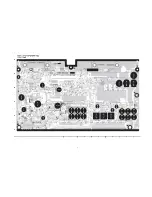
Page 88: ...P BOARD COMPONENT SIDE ETX2MM747MFE 6 5 4 3 2 1 A I B I C I D I E I F I G I H I I 79 ...
Page 90: ...K BOARD FOIL SIDE TXN K1ETUR K BOARD COMPONENT SIDE TXN K1 ETUR F I G I H ...
Page 92: ...A BOARD COMPONENT SIDE A PR42U10 ...
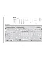
Page 96: ...13 6 SC Board SC BOARD FOIL SIDE TXNSC11XBH A I В I С I D ...
Page 97: ...1 I F I G I H 85 ...
Page 100: ...SC BOARD COMPONENT SIDE TXNSC11XBH 6 5 4 3 2 1 A I B I C I D I E I F I G I H I I 87 ...
Page 103: ...90 ...
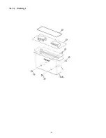
Page 105: ...14 1 2 Packing 1 92 ...
Page 106: ...14 1 3 Packing 2 93 ...


