background image

TX-LR32EM5A

18

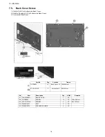
7.5.

Back Cover Screw

1. Stick felt (L & R) at bottom side Back Cover.
2. Stick Sp. Sponge (L & R) at bottom side Back Cover.
3. Fix screw to Back Cover.

Part No

Qty

Location

Torque

THTD030J

12

Back Cover: 12 100±20 N·cm

XTV3+12JFJK

3

AV terminal: 3

60±10 N·cm

No

Item

Description

Qty

UOM

Remarks

01

TKU3FC00501

BACK COVER

1

PC

02

THTD030J

SCREW

12

PC

100 ± 20 N·cm

03

XTV3+12JFJK 

SCREW

4

PC

60 ± 10 N·cm

04

TMK4GA181

FELT

2

PC

05

TMK4GG078

SPEAKER SPONGE

2

PC

Summary of Contents for TX-LR32EM5A

Page 1: ...5 Service Mode 8 5 1 How to enter into Service Mode 8 5 1 1 Contents of adjustment mode 8 5 1 2 How to exit 8 5 2 SRV TOOL 9 5 2 1 How to access 9 5 2 2 Display of SOS History 9 5 2 3 POWER ON TIME COUNT 9 5 2 4 Exit 9 5 2 5 Self Check Mode 10 5 2 6 Self Check Device 10 5 2 7 Hotel Mode Adjustment 10 5 2 8 Hotel Mode 10 6 Troubleshooting Guide 11 6 1 Check of the IIC bus lines 11 6 1 1 How to acce...

Page 2: ...m 30 11 10 A Board 9 16 Schematic Diagram 31 11 11 A Board 10 16 Schematic Diagram 32 11 12 A Board 11 16 Schematic Diagram 33 11 13 A Board 12 16 Schematic Diagram 34 11 14 A Board 13 16 Schematic Diagram 35 11 15 A Board 14 16 Schematic Diagram 36 11 16 A Board 15 16 Schematic Diagram 37 11 17 A Board 16 16 Schematic Diagram 38 11 18 K Board Schematic Diagram 39 11 19 P Board Schematic Diagram 4...

Page 3: ... between the jumpered AC plug and each exposed metallic cabinet part on the equipment such as screwheads connectors control shafts etc When the exposed metallic part has a return path to the chassis the reading should be 100 Mohm and over When the exposed metal does not have a return path to the chassis the reading must be 1 1 2 Leakage Current Hot Check See Figure 1 1 Plug the AC cord directly in...

Page 4: ...posure of the assembly 3 Use only a grounded tip soldering iron to solder or unsolder ES devices 4 Use only an anti static solder removal device Some solder removal devices not classified as anti static ESD protected can generate electrical charge sufficient to damage ES devices 5 Do not use freon propelled chemicals These can generate electrical charges sufficient to damage ES devices 6 Do not re...

Page 5: ...factured using lead free solder will have the PbF within a leaf Symbol PbF stamped on the back of PCB Caution Pb free solder has a higher melting point than standard solder Typically the melting point is 50 70 F 30 40 C higher Please use a high temperature soldering iron and set it to 700 20 F 370 10 C Pb free solder will tend to splash when heated too high about 1100 F or 600 C If you must use Pb...

Page 6: ...5A 6 3 Service Navigation 3 1 Service Hint Board Name Main Device Remarks A BOARD TUN EEP SPI MTK IC Repairable P BOARD Power Supply Power Switch Keyscan Repairable K BOARD Remote LED Luminance Sensor Repairable ...

Page 7: ...bsite English only http panasonic jp support global cs tv PAL 525 60 Playback of NTSC tape from some PAL Video recorders VCR M NTSC Playback from M NTSC Video recorders VCR NTSC AV input only Playback from NTSC Video recorders VCR DVB T Digital terrestrial services MPEG2 and MPEG4 AVC H 264 DVB C Digital cable services MPEG2 and MPEG4 AVC H 264 Aerial input VHF UHF Operating Conditions Temperature...

Page 8: ...s After entering the adjustment mode take note of the value in each item before starting adjustment 5 1 2 How to exit Switch off the power with the POWER button on the main unit or the POWER button on the remote control Main item Sub item Sample Data ADJUST CONTRAST 000 COLOR 59 TINT FE SUB BRT 800 BACKLGT 20D B Y G 40 R Y A 0 VCOM 189 WB ADJ R GAIN 75 G GAIN 80 B GAIN 65 R CENT 80 G CENT 80 B CEN...

Page 9: ... after shipment This indication except 2nd and 1st occurrence after shipment will be cleared by Self check indication and forced to factory shipment setting 5 2 3 POWER ON TIME COUNT Note To display TIME COUNT menu highlight position then press MUTE for 3sec Time Cumulative power on time indicated hour minute by decimal Count Number of ON times by decimal Note This indication will not be cleared b...

Page 10: ...d from wall outlet 4 Explain the Hotel mode setup menu Item TUN yes MEM yes EEPROM yes SOFT yes MODEL ID yes Item Function Mode Select hotel mode off on Input Select input signal modes Set the input when each time power is switched on Selection RF HDMI1 HDMI2 HDMI3 Component Video PC Off give priority to a last memory Channel Select channel when input signal is RF Set the channel each time power i...

Page 11: ...ly Produce TV reception screen and while pressing VOLUME button on the main unit press OK button on the remote control for more than 3 seconds Self check indication and forced to factory shipment setting Produce TV reception screen and while pressing VOLUME button on the main unit press MENU button on the remote control for more than 3 seconds 6 1 2 Exit Disconnect the AC cord from wall outlet 6 1...

Page 12: ...e the defective block can be identified by the number of blinking times of the Power LED on the front panel of the unit as follow 6 3 No Power First check point There are following 2 states of No Power indication by power LED 1 No lit 2 Red is lit then turns red blinking a few seconds later See 6 2 No Name Factor R_LED Blink 1 BL_SOS SOS from PANEL inverter 1 2 TV_SOS SOS from POWER Curcuit 3 3 SO...

Page 13: ...Sp Bracket to cabinet with screw Fig A 2 Stick sponge to Sp Unit Fig B 3 Fix Speaker assy L R to cabinet Fig B No Item Description Qty UOM Remarks 01 L0AA07B00008 SPEAKER UNIT 2 PC 02 TMK4GG076 SP SPONGE 4 PC 03 TKX5ZA02501 SP BRACKET 4 PC 04 XTV3 10JFJ SCREW SP BRKT PANEL 4 PC ...

Page 14: ...TX LR32EM5A 14 7 2 LED Panel Assy 1 Assy LED panel assy LED panel bracket assy and V board to Cabinet complete assy Fig A 2 Fix LCD panel to Cabinet assy ...

Page 15: ...TX LR32EM5A 15 No Item Description Qty UOM 01 TXFKK5Z0004 LED PANEL ASSY 1 PC 02 TXFKK5Z0006 LED BRACKET ASSY 1 PC 03 L5EDDYY00413 LCD PANEL 1 PC 04 TXFKY5Z0413 CABINET ASS Y 1 PC ...

Page 16: ...TX LR32EM5A 16 7 3 Barrier LCD 1 Stick barrier P pcb to LCD Panel 2 Stick gasket to LCD Panel No Item Description Qty UOM 01 TMK4GX134 BARRIER P PCB 1 PC 02 TEWB755 GASKET BTM PANEL 2 PC ...

Page 17: ...t to A print 5 Fix PET tape at K10 A10 wire 1 pc 6 Fix metal bracket bottom 7 Fix bottom cover 8 Fix above part with screw No Item Description Qty UOM Remarks 01 THEJ036J SCREW 11 PC 60 10 N cm 02 TKZ5ZX50311 BOTTOM METAL 1 PC 03 TBX5ZA01701 CONTROL BUTTON 1 PC 04 TKP5ZA24703 SIDE AV BRACKET 1 PC 05 TMX5ZE0021 CHASSIS BRACKET A PCB 2 PC 06 TKP5ZA24101 BOTTOM COVER 1 PC 06 T4FP1505J PET TAPE GREY L...

Page 18: ... 3 Fix screw to Back Cover Part No Qty Location Torque THTD030J 12 Back Cover 12 100 20 N cm XTV3 12JFJK 3 AV terminal 3 60 10 N cm No Item Description Qty UOM Remarks 01 TKU3FC00501 BACK COVER 1 PC 02 THTD030J SCREW 12 PC 100 20 N cm 03 XTV3 12JFJK SCREW 4 PC 60 10 N cm 04 TMK4GA181 FELT 2 PC 05 TMK4GG078 SPEAKER SPONGE 2 PC ...

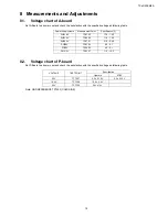
Page 19: ...set and check the satisfaction with the specified voltage as following table Note GND REFERENCE TP7503 COLD SIDE Power Supply Name Measurement Point Specification V SUB1 8V TP8700 1 74 1 90 SUB1 2V TP8000 1 14 1 26 SUB3 3V TP8701 3 19 3 46 SUB5V TP8702 4 9 5 1 STB5V TP5400 4 9 5 1 PNL12V TP8307 11 5 12 5 VOLTAGE TEST POINT Specification Operate STBY 5 3V TP7507 5 3 0 10 V 5 3 0 10 V 16 4V TP7508 1...

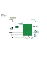
Page 20: ...2 O b d Hi h id EEP_WP EEPROM 64kbit SLV A0 S5 On board USB Slot High side switch TUNER USB1 Silicon Lab IF1 MT5135AE TS ڻھٕیۄہ VIDEO COMPONENT TUNER MT5367 Silicon Lab IIC S1 8V DDR3 1333M 1Gb x16 VIDEO COMPONENT AUDIO VIDEO AUDIO 1333M 2Gb x16 NZ SUB3 3V CS1 SUB3 3V SPI 128Mb Debug UART RST STB5V 27M RST PC HDMI 1 JTAG HDMI 2 SPI 128Mb CS1 RMT KEY LED ...

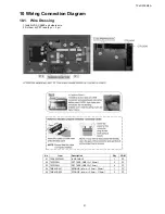
Page 21: ...S CABLE and others wire 2 Fix them by PET tape 4 pc 2 pc No Item Description Qty UOM 01 TSCKF0070001 LVDS CABLE 1 PC 02 T4FP1505J PET TAPE GREY L 100mm 2 PC 03 T4FP1505J PET TAPE GREY L 70mm 4 PC 04 TMK4GG047 SPONGE t 3mm 20mm 30mm 1 PC 04 TMK4GG053 SPONGE t 3mm 25mm 110mm 2 PC ...

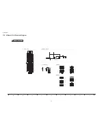
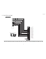
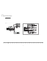
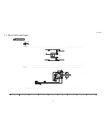
Page 22: ...TX LR32EM5A 22 11 Schematic Diagram 11 1 Schematic Diagram Notes ...

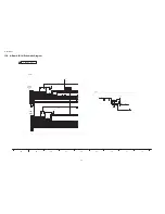
Page 23: ...ER_TUNER_SCL SG_FACT TUNER_DATA STM EEP_SDA MTK_SDA FACT_MODE_SDA STM EEP_SCL MA_TER_TUNER_SDA R0944 EXB28V102JX R0901 2 7k 47k R0975 R0984 0 R0989 2 7k R0970 47k R0972 100 R0974 47k R0985 0 R0907 2 7k R0988 2 7k R0906 2 7k R0900 2 7k R0973 100 R0968 22k JS0015 JS0027 C0085 0 1u 16V SUB5V I2C MTK IIC_0 Normal SCL GND Normal SDA Factory Adj Connector To 800sht USBBOOT STM_SRQ DEBUG SERIAL LCD_EEP_W...

Page 24: ...4900 VJ4805 VJUMP1608 P VJ4806 VJUMP1608 P TP4800 TP4801 IF1_P MA_TER_TUNER_SCL IF2_P IF1_N FE_RST AGC_2 IF2_N MA_FE_RST TUNER_AIF_INN IF1_N IF2_N IF2_P TUNER_AIF_INP TUNER_DIF_INP IF1_P MA_FE_RST TUNER_DIF_INN SITU_SDA MA_TER_TUNER_SDA SITU_SCL R4898 22 R6006 100 R4899 22 R6017 100 R4875 820 R4845 220 R4876 820 R6007 100 TU4802 ENVS9301D5F NC 2 IFAGC2 3 IF2_P 4 IF2_N 5 VB1 6 Reset 7 SDA 8 SCL 9 V...

Page 25: ...3 L4902 G1C150MA0533 L4901 G1C150MA0533 R4923 R4930 R4931 TP4901 TP4903 TP4902 TP4900 DCDC_EN AMP_XRST I2S_MCLK I2S_BCLK I2S_SDIN AU_RP AMP_STBY I2S_LRCLK AU_LP AU_LM AU_RM AU_LP AU_LM AU_RM SOUND_SOS AU_RP R4913 150 R4915 150 R4914 150 R8158 0 R4912 150 R4924 0 R4925 0 C1AB00003871 IC4900 1 SDATA 2 BLCK 3 LRCLK 4 RSTK 5 MUTEX 6 REG_G 7 REG3 8 FILP 9 FILA 10 GNDA 11 OUT1N 12 OUT1N 13 GNDP1 14 OUT1...

Page 26: ...CI_VS1 CI_IN_DATA7 CI_IN_DATA3 M_CI_IREQ CI_IN_SYNC CI_INPACK CI_WAIT CI_RST CI_WAIT CI_WAIT CI_OUT_DATA7 CI_INPACK CI_OUT_DATA3 CI_CE1 M_CI_OUT_SYNC M_CI_OUT_CLK CI_OUT_DATA2 CI_CD 1 M_CI_OUT_DATA3 CI_OUT_DATA5 CI_IN_DATA5 M_CI_OUT_DATA1 CI_OUT_SYNC CI_IREQ M_CI_CD2 M_CI_OUT_DATA4 CI_OUT_CLK CI_IN_DATA6 CI_OE CI_OUT_CLK M_CI_OUT_DATA0 M_CI_OUT_VALID CI_IN_CLK M_CI_OUT_DATA7 M_CI_VS1 CI_CD2 CI_IN_...

Page 27: ...0 TP4111 TP4098 TP4099 TP4091 TP4109 TP4108 TP8307 TP4106 TP4107 AE2P AO1N AO0P AE0P AO4P AE3P AO0N AE3N AO3P AOCLKP AECLKP AO2N AO4N AE2N AO5P AE5N AO1P AECLKN AOCLKN AE4P AE0N AO2P AE5P AE4N AE1P AO5N AO3N AE1N DCDC_EN AMP_XRST R4155 0 R8390 100 R4159 0 R4154 0 R4156 0 R8393 1 5k 1 R8391 21 5k 1 R4106 0 R4150 1k PANEL12V for LVDS Panel MTK 01 02 03 04 05 06 07 08 09 10 11 12 13 14 15 16 17 18 19...

Page 28: ...u R3127 0 L3128 J0JYC0000331 R3228 10k 1 MON_L_IOC L3127 J0JYC0000331 C3190 50V 560p C3205 50V 10p R3211 75 1 5 R3208 220 Q3107 B1ABCF000231 C3206 50V 10p R3227 51k 1 R3231 0 L3125 J0JYC0000331 CVBSIN1 Y1 1 R3226 75 Q3106 B1ABCF000231 G2 YIN2 FBIN2 O2 C3187 16V 0 01u JK1003 K1FY121A0017 1 2 3 4 5 6 7 8 9 10 11 12 13 14 15 16 17 18 19 20 21 R3220 5 1k L3124 J0JCC0000287 R2 CIN1 C3204 50V 47p C3191 ...

Page 29: ...000230 IC3001 1 A_OUTPUT 2 A INPUT 3 A INPUT 4 V 5 B INPUT 6 B INPUT 7 B_OUTPUT 8 V C1AB00003391 IC2110 1 C1P 2 PGND 3 C1N 4 NC 5 PVSS 6 NC 7 SVSS 8 NC 9 OUTL 10 SVDD 11 OUTR 12 NC 13 INL 14 SDR 15 INR 16 NC 17 SGND 18 SDL 19 PVDD 20 NC Exposed_Pad JK2102 K2HC104E0021 1 2 3 4 5 5 L3012 J0JHC0000075 SUB3 3V P15V SUB3 3V R2199 VJ2100 ALSPOUT EXT1_MUTE MON_L_OUT SPDIF_OUT ARSPOUT MON_R_OUT MON_L_IOC ...

Page 30: ...X0CP P_RX1CP P_RX1P1 P_RX0P1 HDMI_0_SDA HDMI_CEC HDMI_0_HPD HDMI_1_SDA HDMI_1_HPD Q2004 B1ABCE000015 Q4702 B1ABCE000015 Q2005 B1ABCE000015 Q4703 B1ABCE000015 Q4513 B1ADCF000194 Q4514 B1HFCEA00001 R4745 EXB28V473JX R4720 100 1 10W R4552 56 R4548 22 R4721 10k R4715 10k R2034 47k R4724 1k R4717 100 1 10W R4560 47k R4744 10k R4551 150 R4554 1k R4550 150 R4747 10k R4722 100 1 10W R4748 1k R4749 22 R810...

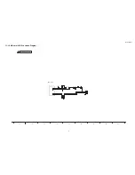
Page 31: ...0V C5629 16V 0 1u C5626 220u 6 3V C0DBZYY00368 IC5603 1 Vin 2 GND 3 EN 4 FLG 5 Vout JK1031 K1FY104E0002 1 2 3 4 L5606 J0JHC0000045 SUB3 3V SUB5V TP5604 TP5603 USB0VBUS USB0OD USB0DP USB0DN R5610 D1HYR004A024 R5608 10k R5609 10k USB_SIDE MTK 79 73 74 77 78 76 80 75 81 A BOARD 9 16 ...

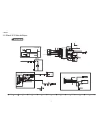
Page 32: ...R4859 22k R5004 10k 1 16W R2014 10k R4816 2 2k R5177 2 2k R5175 68 D2001 EZJZ0V120JA BL_ON PWM_EN KEY1 R2803 47k Q2800 B1ABCE000015 AI_SENSOR_ADIN TP2001 P15V R2801 47k R2009 1k Q2801 B1ABCE000015 TP2012 R1953 10k R2031 10k TP2015 RMIN KEY3 A10 K1KA07B00135 1 2 3 4 5 6 7 C2754 1000p 50V R2033 10k R4728 TP2774 R_LED_ON TP2011 BL_SOS SUB3 3V TP2013 R2752 R2804 10k TP2775 TP2770 A09 1 2 3 4 5 6 7 8 9...

Page 33: ...OLD 2 VCC 3 NC 4 NC 5 NC 6 NC 7 CS 8 DO 9 WP 10 GND 11 NC 12 NC 13 NC 14 NC 15 DI 16 CLK SUB3 3V SUB3 3V SUB3 3V TP8005 TP8004 TP8013 TP8010 TP8003 TP8007 TP8011 TP8006 SPI_DIN SPI_CS0 SPI_CK SPI_DIN SPI_CK SPI_CS1 SPI_DOUT SPI_DOUT EEP_WP STM EEP_SCL STM EEP_SDA R8100 10k R8240 10k R8099 1k R8153 10k R8154 10k R8155 4 7k R8156 4 7k R8103 10k SPI_FLASH EEPROM_STM 64Kbit I2CBUS EEPROM SPI 16MB 128M...

Page 34: ... SW 2 PGND 3 VINA 4 EN 5 FB 6 AGND 7 GND 8 VINSW IC8704 C0DBAYY01273 1 SW 2 PGND 3 VINA 4 EN 5 FB 6 AGND 7 GND 8 VINSW IC8700 C0DBAYY01273 1 SW 2 PGND 3 VINA 4 EN 5 FB 6 AGND 7 GND 8 VINSW L8708 J0JYC0000464 L8704 G1C6R8MA0426 L8701 G1C4R7ZA0240 G1C6R8MA0426 L8700 L8703 G1C4R7ZA0240 P15V SUB3 3V STB5V P15V P15V P15V SUB3 3V 5 8VS P15V ADAC3 3V SUB3 3V SUB1 2V SUB5V SUB5V SUB3 3V VCCK1 1V VCCK1 2V ...

Page 35: ... VCCK1 1V ADAC3 3V R8112 R8012 R8013 VJ6703 R8038 R8014 VJ6701 R8010 VJ8002 R8017 R8007 VJ8000 VJ6702 VJ8003 L8006 VJUMP2012 P R8004 VJ8001 VJ8005 R8005 R8006 VJ6705 R8002 VJ8414 L8049 VJUMP1608 P VJ6704 VJ4000 R8015 R8025 VJ8004 R8018 L8050 VJUMP1608 P R8009 AVDD1V2_HDMI1 AVDD12_DEMOD AVDD12_RGB AVDD12_VPLL AVDD12_REC AVDD1V2_HDMI2 5135_DV10 VCCK AVDD3V3_PLLGP DDRV AVDD33_AADC AVDD33_PDM_STB AVDD...

Page 36: ...R9 VDD IC8200 R3 A9 IC8200 L2 CS IC8200 J1 NC IC8200 D9 VDD IC8200 N1 VDD IC8200 D2 VDDQ IC8200 T1 VSS IC8200 M9 VSS IC8200 M3 BA2 IC8200 N3 A0 IC8200 T7 NC IC8200 T9 VSS IC8200 E3 DQL0 IC8200 P9 VSS IC8200 B8 DQU6 IC8200 N9 VDD IC8200 B3 VSS IC8200 A7 DQU4 IC8200 B1 VSSQ IC8200 D8 VSSQ IC8200 C7 DQSU IC8200 C3 DQU1 IC8200 R8 A6 IC8200 A8 VDDQ IC8200 F2 DQL2 IC8200 C2 DQU3 IC8200 D3 DMU IC8200 A9 ...

Page 37: ...A12 100 A25 101 A7 102 VS2_ 103 A6 104 PCMCIA_RESET 105 A5 106 WAIT_ 107 A4 108 A3 109 DVSS 110 DVDD33 111 REG_ 112 DVSS 113 DVDD10 114 A2 115 BVD2 116 A1 117 BVD1 118 A0 119 D8 120 D0 121 D9 122 D1 123 D10 124 D2 125 CD2_ 126 CI_INT 127 DVSS 128 DVDD33 SPI_DATA M_CI_OUT_VALID TUNER_DIF_INN M_CI_OE FE_RST M_CI_OUT_CLK M_CI_OUT_DATA2 M_CI_OUT_DATA7 M_CI_IORD M_CI_INT M_CI_OUT_DATA4 M_CI_OUT_DATA3 M...

Page 38: ...13 RDQS1_ 214 VCC2IO 215 RDQ12 216 RDQ14 217 RDQ10 218 RDQ8 219 RDQ1 220 VCC2IO 221 RDQ3 222 RDQ7 223 RDQ5 224 VCCK 225 AVDD12_REC 226 REXT 227 AVDD33_COM 228 RXVN 229 RXVP 230 TXVN 231 TXVP 232 AVDD33_LD 233 USB_DM0 234 USB_DP0 235 AVDD33_USB 236 USB_DM1 237 USB_DP1 238 VCCK 239 AVDD33_HDMI_1_RX 240 HDMI_0_RX_CB 241 HDMI_0_RX_C 242 HDMI_0_RX_0B 243 HDMI_0_RX_0 244 HDMI_0_RX_1B 245 HDMI_0_RX_1 246...

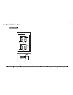
Page 39: ...TX LR32EM5A 39 11 18 K Board Schematic Diagram 6 5 4 3 2 1 A B C D E F G H I ...

Page 40: ...TX LR32EM5A 40 11 19 P Board Schematic Diagram 6 5 4 3 2 1 A B C D E F G H I ...

Page 41: ...5104 CN0100 Q2800 Q2801 IC8001 I C 8 2 0 0 IC3001 A09 JK4800 A10 A 1 2 A 1 6 JK2102 A 2 1 D E F J K L M M L K J H G F E D C B A Y X W V U T S R Q P N Upper Lower T N P 4 G 5 3 5 A A B C G H 1 1 A A 1 32 1 1 9 1 19 1 2 0 1 2 1 2 1 2 0 1 4 8 1 8 1 8 1 8 1 3 6 3 5 2 1 6 8 6 7 3 4 3 3 1 9 1 19 1 32 1 1 14 S U F F I X 256 1 A 1 8 1 1 12 1 7 1 4 1 51 1 32 A Ref No Location Ref No Location Ref No Locatio...

Page 42: ...Q 4 9 0 2 JK3000 Q 2 0 0 7 Q 5 1 0 1 Q5103 I C 8 0 0 4 I C 8 0 0 7 IC8404 JK4800 A12 J K 2 1 0 2 TNP4G535 A 1 IF2P B2 SDA B3 IF1P SCL IF1N 1 1 2 8 IF2P VB1 SDA VB2 IF1P IFAGC2 IF2N SCL IFAGC1 IF1N 2 1 21 20 1 3 2 16 1 8 1 2 1 3 5 3 6 3 3 3 4 6 7 6 8 R E V E R S E F O R S U F F I X S E E 16 1 8 1 1 4 A Ref No Location Ref No Location Ref No Location IC5000 A5 IC8100 C6 D3050 D2 IC5416 B6 IC8301 D6 ...

Page 43: ...2811 D2801 D2802 D2803 D2804 R2800 D2805 R2803 R2804 R2805 R2806 R2807 R2808 R2809 R2810 R2811 R2812 R2813 RM2800 D2800A D2800B T P 8 0 0 T P 8 0 1 T P 8 0 2 T P 8 0 3 T P 8 0 4 T P 8 0 6 T P 8 0 7 T P 8 0 8 T P 8 0 9 R M 8 0 0 1 K C R N O 2 T N P A 5 7 1 9 F O R S U F F I X S E E R E V E R S E RM2800A TP2800 TP2801 TP2802 TP2803 TP2804 TP2806 TP2807 TP2808 TP2809 RM2800 K Ref No Location D2800A C...

Page 44: ...D 7 3 0 3 C L 7 1 2 4 CL7112 T P 7 5 0 9 T P 7 1 0 5 C L 0 1 4 R 7 5 1 1 R7317 R7505 D7504 R 7 3 0 4 R 7 1 0 3 C 7 3 1 2 C L 7 1 5 0 CL7140 CL7119 C L 0 6 2 CL017 R 7 5 1 7 R 7 5 1 2 D 7 5 1 0 R 7 3 1 2 C 7 5 2 2 C 7 5 1 6 Q 7 3 0 4 JA2 C L 7 1 1 0 T P 7 5 0 7 CL060 R 7 4 0 4 C L 0 1 3 R 7 3 4 4 R 7 3 2 1 R7504 R 7 3 0 3 C7311 C L 7 1 3 8 C L 7 1 0 9 T P 7 5 0 6 T P 7 1 0 3 R 7 4 0 3 R7343 R 7 5 2...

Page 45: ... 7 5 2 8 R 7 3 3 5 R7529 F7101 R7530 R7342 R7343 R 7 3 4 4 C F 7 1 0 1 C F 7 1 0 2 C 7 4 0 1 C7402 P 2 P3 S W 7 4 0 1 S W 7 4 0 2 SW7403 SW7404 SW7405 SW7406 D 7 4 0 1 D 7 4 0 2 R 7 4 0 2 R 7 4 0 3 R 7 4 0 4 R 7 4 0 5 L 7 1 0 1 L7102 L 7 3 0 1 L 7 3 0 2 C7832 C 7 8 3 3 C7834 L F 7 1 0 3 L F 7 1 0 4 JK7101 JK7102 D 7 3 1 5 D7321 T P 7 5 0 7 TP7504 T P 7 5 0 1 T P 7 1 0 6 T P 7 8 0 3 TP7502 T P 7 5 ...

Page 46: ... and Replacement Parts List 13 1 Exploded View and Mechanical Replacement Parts List Please click the radio button for Diagrams ll Parts List on the menu bar 13 2 Electrical Replacement Parts List 13 2 1 Replacement Parts List Notes ...

Page 47: ...200 F1G1H1020008 C 1000PF 50V C3204 F1G1H470A834 C 47PF C3205 F1G1H100A833 C 10PF 50V C3206 F1G1H100A833 C 10PF 50V C3207 F1G1H100A833 C 10PF 50V C3208 F1G1H561A830 C 560 pF 50 V C3209 F1G1H561A830 C 560 pF 50 V C4085 F1G1C104A077 C 0 1UF 16V C4548 F1G1A105A047 C 1UF 10V C4781 F1G1C104A077 C 0 1UF 16V C4802 F1J1A106A087 C 10UF C4804 F1J1A106A087 C 10UF C4856 F1H1C105A145 C 1 uF 16 V C4857 F1H1C105...

Page 48: ... C8215 F1G1C104A077 C 0 1UF 16V C8216 F1G1C104A077 C 0 1UF 16V C8228 F1J1A106A087 C 10UF C8229 F1G1C104A077 C 0 1UF 16V C8230 F1G1C104A077 C 0 1UF 16V Safety Ref No Part No Part Name Description Remarks C8231 F1G1C104A077 C 0 1UF 16V C8232 F1G1C104A077 C 0 1UF 16V C8233 F1G1C104A077 C 0 1UF 16V C8234 F1G1C104A077 C 0 1UF 16V C8355 F1JZZ1060001 C 10UF C8357 F1JZZ1060001 C 10UF C8360 F1JZZ1060001 C ...

Page 49: ...8051 J0JCC0000245 BEAD CORE L8317 G1C100MA0426 INDUCTOR L8700 G1C6R8MA0426 COIL L8701 G1C4R7ZA0240 INDUCTOR L8703 G1C4R7ZA0240 INDUCTOR L8704 G1C6R8MA0426 COIL L8708 J0JYC0000464 BEAD CORE TRANSISTOR Q2003 B1ABCE000015 TRANSISTOR Q2004 B1ABCE000015 TRANSISTOR Q2005 B1ABCE000015 TRANSISTOR Q2007 B1ABCE000015 TRANSISTOR Q2800 B1ABCE000015 TRANSISTOR Q2801 B1ABCE000015 TRANSISTOR Q3106 B1ABCF000231 T...

Page 50: ...D0GA560JA023 M 56 OHM R4554 D0GA102JA023 M1KOHM Safety Ref No Part No Part Name Description Remarks R4560 D0GA473JA023 M 47KOHM R4563 D0GA103JA023 M10KOHM R4715 D0GA103JA023 M10KOHM R4716 D0GB101JA069 M 100 OHM R4717 D0GB101JA069 M 100 OHM R4720 D0GB101JA069 M 100 OHM R4721 D0GA103JA023 M10KOHM R4722 D0GB101JA069 M 100 OHM R4724 D0GA102JA023 M1KOHM R4726 D0GB101JA069 M 100 OHM R4727 D0GB101JA069 M...

Page 51: ... D1BA2400A023 M 240 OHM Safety Ref No Part No Part Name Description Remarks R8224 D1H81014A042 M 100 OHM R8225 D1H81014A042 M 100 OHM R8226 D1BA1001A023 M 1 KOHM R8227 D1BA1001A023 M 1 KOHM R8240 D0GA103JA023 M10KOHM R8242 D1H81014A042 M 100 OHM R8243 D1H81014A042 M 100 OHM R8244 D1H81014A042 M 100 OHM R8245 D1H81014A042 M 100 OHM R8390 D0GA101JA023 M 100 OHM R8391 D1BA2152A023 M 21 5KOHM R8393 D1...

Page 52: ...SWITCH SW7404 EVQ11G05R SWITCH SW7405 EVQ11G05R SWITCH SW7406 EVQ11G05R SWITCH TU4802 ENVS9301D5F TUNER X6700 H0J270500137 RESONATORS X8301 H0J270500137 RESONATORS ZA7101 K4AD01A00004 RUG TERMINAL ZA7102 K4AD01A00004 RUG TERMINAL Safety Ref No Part No Part Name Description Remarks ...

Page 53: ...Model No TX LR32EM5A Parts Location ...

Page 54: ...Model No TX LR32EM5A Packing Exploded View ...

Page 55: ...KP5ZA24101 BOTTOM COVER TKP5ZA24703 SIDE AV BRACKET 5 TKU3FC00501 BACK COVER TKX5ZA02501 SPEAKER BRACKET 6 TPC3FA00401 PACKING CASE TPD3FA00071 TOP CUSHION TPD3FA00081 BOTTOM CUSHION TPD3FA00091 TOP CENTER CUSHION TPD3FA00101 BOTTOM CENTER CUSHION TPE4GH065 SET COVER TQZ4GB642 FAN BAG ASSY TSCKF0070001 LVDS CABLE TXFKK5Z0004 LED PANEL ASSY TXFKK5Z0006 LED BRACKET ASSY 7 TXFKY5Z0413 CABINET ASSY XS...

Reviews: