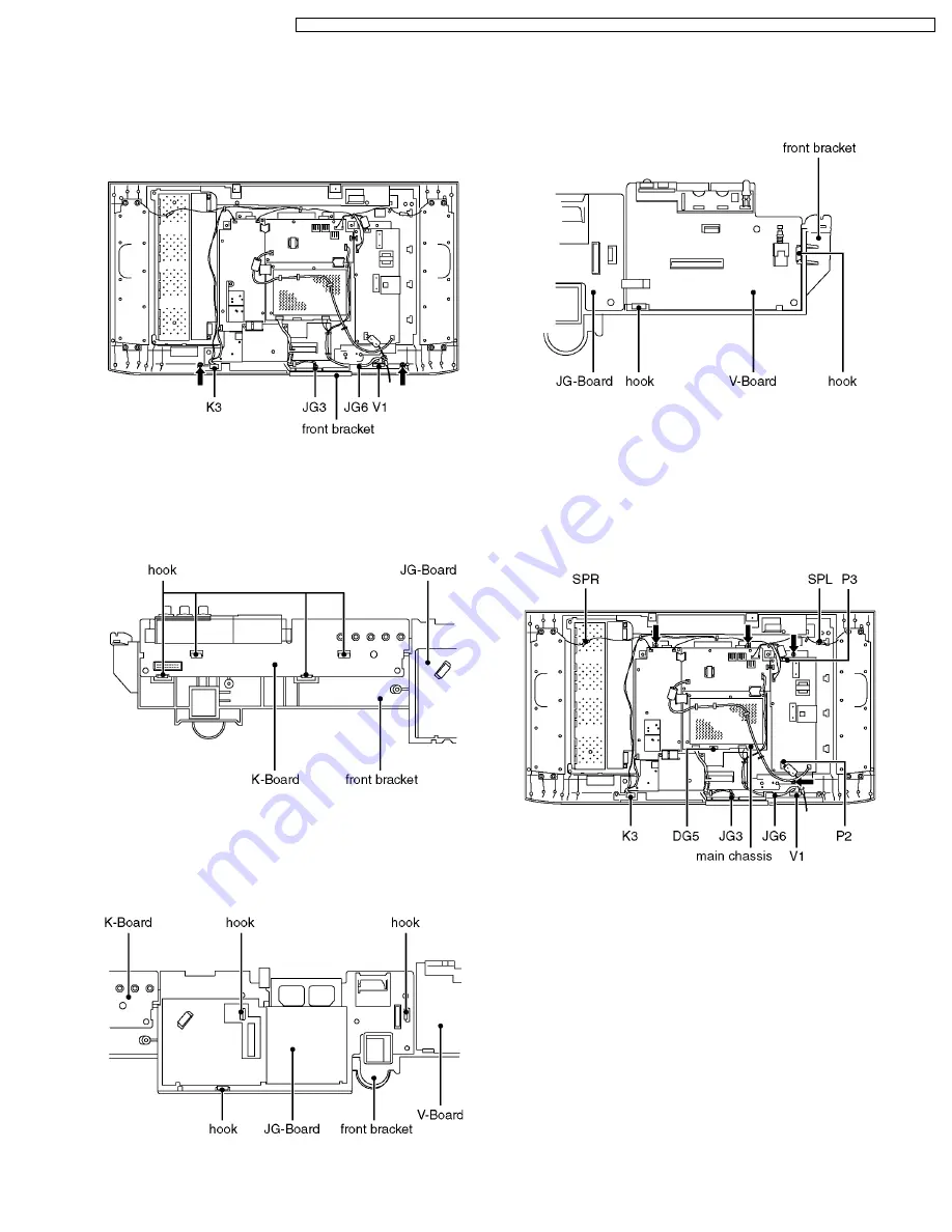
6.13. Front bracket
1. Remove the rear AV bracket ass´y (See 6.3.) and the rear
metal frame. (See 6.4.)
2. Disconnect the couplers (K3, JG3, JG6 and V1).
3. Remove the fixing screws (2pcs).
4. Remove the front bracket.
6.14. K-Board
1. Remove the front bracket. (See 6.13.)
2. Remove the hooks (4place).
3. Remove the K-Board.
6.15. JG-Board
1. Remove the front bracket. (See 6.13.)
2. Remove the hooks (3place).
3. Remove the JG-Board.
6.16. V-Board
1. Remove the front bracket. (See 6.13.)
2. Remove the hooks (2place).
3. Remove the V-Board.
6.17. Main chassis
1. Remove the rear AV bracket ass´y (See 6.3.) and the rear
metal frame. (See 6.4.)
2. Disconnect the couplers (K3, JG3, JG6, V1, P2, P3, SPL
and SPR) and the flexible cables (DG5).
3. Remove the fixing screws (4pcs).
4. Remove the main chassis.
·
·
·
·
Disconnecting flexible cable from the coupler.
Lift up both ends of the cable lock (brown colored)
simultaneously to release the locking. Once the flat cable is
disconnected from the coupler, the cable lock tends to
detach from the coupler easily. Due precaution should be
paid on it.
·
·
·
·
Reconnecting flexible cable to the coupler.
Attach the cable lock (brown) to the coupler (white) with its
both ends being pulled up. Insert the flat cable into the
coupler over the cable lock until the cable stops firmly at the
coupler end. Press down both ends of the cable lock until
their upper faces are positioned flat to lock the cable.
13
TX-32LX1X / TX-32LX1M / TX-32LX1A / TX-32LX1T / TC-32LX1H / TC-32LX1DJ / TX-26LX1X / TX-26LX1M / TX-26LX1A / TX-26LX1T / TC-26LX1H


