


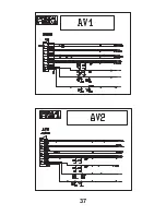
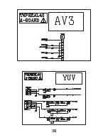
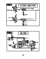
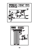
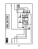
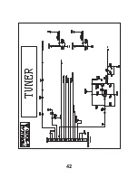
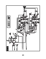
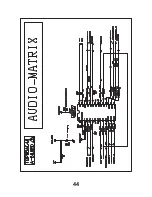

SCHEMATIC DIAGRAMS FOR MODELS
TX-32LXD60, TX-26LXD60
(GLP21 CHASSIS)
NOTE
1. RESISTOR
All resistors are carbon ¼W resistor, unless marked otherwise.
Unit of resistance is OHM (
Ω
) (k=1,000, M=1,000,000)
2. CAPACITORS
All capacitors are ceramic 50V unless marked otherwise.
Unit of capacitance is
µ
F unless otherwise stated.
3. COIL
Unit of inductance is
µ
H, unless otherwise stated.
4. TEST POINT
Test Point Position
5. EARTH SYMBOL
Chassis Earth (Cold)
Line Earth (Hot)
6. VOLTAGE MEASUREMENT
Voltage is measured by a D.C. voltmeter.
Measurement conditions are as follows:
Power source
220V-240V AC, 50Hz
Receiving Signal
Colour Bar signal (RF)
All customer controls Maximum position
7.
Indicates the Video signal path
Indicates the Audio signal path
These schematic diagrams are the latest at time of printing and are subject to change without notice.
REMARKS
a. Do not touch the hot part, or the hot and cold parts at the same time, as you are liable to a shock hazard.
b. Do not short circuit the hot and cold circuits as electrical components may be damaged.
c. Do not connect an instrument, such as an oscilloscope, to the hot and cold circuits simultaneously as this may cause
fuse failure. Connect the earth of the instruments to the earth connection of the circuit being measured.
d. Make sure to disconnect the power plug before removing the chassis.
NOTE
1. The Power Supply Circuit contains a circuit area, which uses a separate power supply to isolate the earth connection.
The circuit is defined by HOT and COLD indications in the schematic diagram. All circuits, except the Power Circuit, are
COLD.
IMPORTANT SAFETY NOTICE
Components identified by mark have special characteristics
important for safety. When replacing any of these components, use
only manufacturers' specified parts.
30
Summary of Contents for TX-26LXD60
Page 29: ...29 NOTES ...
Page 31: ...31 ...
Page 32: ...32 ...
Page 33: ...33 ...
Page 34: ...34 ...
Page 35: ...35 ...
Page 36: ...36 ...
Page 37: ...37 ...
Page 38: ...38 ...
Page 39: ...39 ...
Page 40: ...40 ...
Page 41: ...41 ...
Page 42: ...42 ...
Page 43: ...43 ...
Page 44: ...44 ...
Page 45: ...45 ...
Page 46: ...46 ...
Page 47: ...47 ...
Page 48: ...48 ...
Page 49: ...49 ...
Page 50: ...50 ...
Page 51: ...51 ...
Page 52: ...52 ...
Page 53: ...53 ...
Page 54: ...54 ...
Page 55: ...55 ...
Page 56: ...56 ...
Page 57: ...57 ...
Page 58: ...58 ...
Page 59: ...59 ...
Page 60: ......
Page 61: ...60 TNPA3740 XV BOARD XV BOARD SCHEMATIC DIAGRAM IS NOT INCLUDED IT IS ONLY EXCHANGE UNIT ...


