background image

(16:9 MODE) ADJUSTMENT / CONFIRMATION

 1. V-ZOOM (16:9) ADJUSTMENT

(Service 3)

*a. Receive PAL monoscope pattern E11. (If no burst signal : Set to force PAL)

b. Set the aspect to 16:9.

c. Confirm that A, B in Fig. 1 is 4.0 cm ± 1.5, if not, adjust V-ZOOM.

d. Receive NTSC monoscope patern US13. (If no burst signal : Set to force NTSC)

c. Confirm that A, B in Fig. 1 is *a, if not, adjust V- ZOOM.

Fig. 1

16

TX-21RX25R

Summary of Contents for TX-21RX25R

Page 1: ...lectric Industrial Co Ltd All rights reserved Unauthorized copying and distribution is a violation of law TX 21RX25R GP41Z Chassis Video Audio Terminal DVD Y 1 0 Vp p 75 PB 0 7 Vp p 75 PR 0 7 Vp p 75...

Page 2: ...stment for CRT CUT OFF 7 2 5 Adjustment Procedure 7 2 6 Adjustment of Purity 8 3 Location of Lead Wiring 20 3 1 Wire Dressing 20 3 2 Wire Dressing and Connections 21 4 Conductor Views 22 5 Schematic D...

Page 3: ...ing the tube After servicing make the following leakage current check to prevent the customer from being exposed to shock hazards 1 2 Leakage Current Cold Check 1 Unplug the power cord and connect a j...

Page 4: ...calibrated high voltage meter 1 Set the brightness to minimum 2 Use the remote to get into Service Mode 3 Measure the EHT The meter reading should indicate 24 0 1 5 kV If the meter indication is out o...

Page 5: ...01 R G B SCL SDA CVBS IN REAR INPUTS AV1 V L R AV3 YUV V L R VCT IF IC601 V_IN CVBS OUT MON_OUT R G B R G B MON_OUT V L R EEPROM IC1101 SCL SDA A_IN IF H A AUDIO OUT V SPEAKER AUDIO AMP IC2301 V OUT T...

Page 6: ...OK Store Save selected item Normalize Exit service mode 3 Service Mode 2 Controls To enter SERVICE 2 press channel key 1 in SERVICE 1 entry screen Key 3 4 Previous Next Service 2 Item Key 8 9 Toggle...

Page 7: ...0 263 0 003 nit 3 Adjustment B Drive so that Y 0 261 0 003 nit 2 4 Adjustment for CRT CUT OFF Preparation 1 Connect the oscilloscope probe to TPL5 2 Screen VR min 3 Set the data Sub Bright Bright 4 I...

Page 8: ...eive the purity pattern White pattern d Picture menu CONTRAST Max BRIGHT Max e Set V CENTER to 4 f Static convergence should have been roughly adjusted g Connect DC current meter through FBT pin 3 and...

Page 9: ...stment secure magnets with magnet lock of white lacquer Beams move with rotating when static magnet is turned Rotational reduce of beams differs by angle of two magnets Therefore repeat magnet adjustm...

Page 10: ...position VRS Mag Set VRS Mg that 2 magnets are top position c Set geomagnetic correction DAC As in TABLE 1 2 ADJUSTMENT a Receive the white balance pattern b Adjust V CENTER c Set R B CUT OFF to mini...

Page 11: ...RESET MENU b Confirm that it leans right side as shown Fig 1 when change the DAC c Confirm that it leans left side as shown Fig 1 when change the DAC d Confirm that purity is changed when change the D...

Page 12: ...ADJUSTMENT 1 PREPARATION a Receive crosshatch pattern E 4 b Picture menu DYNAMIC NORMAL 2 ADJUSTMENT a Adjust focus VR for best position Adjust focus base on no 6 line Fig 1 Crosshatch Pattern 12 TX 2...

Page 13: ...YNAMIC Normal 3 CONFIRMATION AND ADJUSTMENT a Adjustment of 50 Hz V CENTER a Receive the monoscope pattern E11 b Adjust V POS so that centre of monoscope pattern is at CRT centre b Adjustment of 50 Hz...

Page 14: ...Receive the Philips pattern US11 b Adjust V POS so that centre of Philips pattern is at 2 3 of Top and Bottom A B Fig 3c is 2 3 of viewable size b Adjustment of 50 Hz V AMP a Receive the Philips patt...

Page 15: ...just H AMP so that both edges are within 2 5 0 2 Refer to Fig 1 Fig 1 5 EW ADJUSTMENT CONFIRMATION a PREPARATION a Receive crosshatch pattern E4 b EW ADJUSTMENT a Adjust the vertical line no 2 to stra...

Page 16: ...cope pattern E11 If no burst signal Set to force PAL b Set the aspect to 16 9 c Confirm that A B in Fig 1 is 4 0 cm 1 5 if not adjust V ZOOM d Receive NTSC monoscope patern US13 If no burst signal Set...

Page 17: ...C D Fig 3 is 2 0 0 1 A B Fig 3 is 2 0 0 1 Fig 3 c Adjustment of 60 Hz H CENTER a Receive the monoscope pattern US13 b Adjust H POS 60 Hz offset so that horizontal position is at centre of CRT d Adjust...

Page 18: ...justment of TRAPEZOID a Adjust the vertical line to straight line of both sides of vertical lines trapezoid in Fig 3 by TRAPEZ 1 Fig 3 4 Adjustment of UPPER CORNER AND LOWER CORNER a Adjust the EW at...

Page 19: ...6 Adjustment of BOW a Adjust BOW so that the vertical lines are straight Fig 6 Fig 6 19 TX 21RX25R...

Page 20: ...3 Location of Lead Wiring 3 1 Wire Dressing 20 TX 21RX25R...

Page 21: ...0 WIRE MUST BE INSERTED AT G BOARD AND K B0ARD CONNECTERS SINGLE CLAMP DOUBLE CLAMP SAFETY CAUTION POINTS 1 ALL LEAD MUST NOT TOUCH THE HIGH TEMPERATURE PARTS HEAT SINK FBT POWER CIRCUIT 2 DY LEAD MUS...

Page 22: ...4 Conductor Views 22 TX 21RX25R...

Page 23: ...ise noted 3 Coil Unit of inductance is H unless otherwise noted 4 Test Point Test Point position 5 Earth Symbol Chassis Earth Cold Line Earth Hot 6 Voltage Measurement Voltage is measured using DC vol...

Page 24: ...ons in the schematic diagram Take the following precautions All circuits except the Power Circuit are cold Precautions a Do not touch the hot part or the hot and cold parts at the same time or you may...

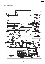
Page 25: ...5 1 A Board 5 1 1 A Board 1 5 1A 2A 3A 5A 4A 6A 7A 8A 25 TX 21RX25R...

Page 26: ...5 1 2 A Board 2 5 1B 2B 3B 4B 5B 6B 7B 1A 2A 3A 5A 4A 6A 7A 8A 26 TX 21RX25R...

Page 27: ...5 1 3 A Board 3 5 1C 2C 3C 4C 5C 6C 8C 7C 1B 2B 3B 4B 5B 6B 7B 27 TX 21RX25R...

Page 28: ...5 1 4 A Board 4 5 1D 2D 3D 4D 5D 7D 8D 9D 6D 1C 2C 3C 4C 5C 6C 8C 7C 28 TX 21RX25R...

Page 29: ...5 1 5 A Board 5 5 1D 2D 3D 4D 5D 7D 8D 9D 6D 29 TX 21RX25R...

Page 30: ...5 2 L Board 5 2 1 L Board 1 3 1A 2A 3A 4A 5A 30 TX 21RX25R...

Page 31: ...5 2 2 L Board 2 3 1B 2B 3B 4B 1A 2A 3A 4A 5A 31 TX 21RX25R...

Page 32: ...5 2 3 L Board 3 3 1B 2B 3B 4B 32 TX 21RX25R...

Page 33: ...5 3 V Board 5 3 1 V Board 1 2 1A 2A 3A 4A 33 TX 21RX25R...

Page 34: ...5 3 2 V Board 2 2 1A 2A 3A 4A 34 TX 21RX25R...

Page 35: ...5 4 PP Board 5 4 1 PP Board 1 2 1A 2A 3A 5A 4A 6A 7A 8A 35 TX 21RX25R...

Page 36: ...5 4 2 PP Board 2 2 1A 2A 3A 5A 4A 6A 7A 8A 36 TX 21RX25R...

Page 37: ...5 5 G Board 5 5 1 G Board 1 2 1A 2A 3A 4A 5A 6A 7A 8A 9A 37 TX 21RX25R...

Page 38: ...5 5 2 G Board 2 2 1A 2A 3A 4A 5A 6A 7A 8A 9A 38 TX 21RX25R...

Page 39: ...5 6 K Board 5 6 1 K Board 39 TX 21RX25R...

Page 40: ...5 7 P Board 5 7 1 P Board 40 TX 21RX25R...

Page 41: ...5 8 SW Board 5 8 1 SW Board 1 2 1A 2A 3A 41 TX 21RX25R...

Page 42: ...5 8 2 SW Board 2 2 1A 2A 3A 42 TX 21RX25R...

Page 43: ...6 Parts Locations 6 1 Packing Exploded View A 43 TX 21RX25R...

Page 44: ...6 2 Packing Exploded View B 44 TX 21RX25R...

Page 45: ...6 3 Parts Locations 45 TX 21RX25R...

Page 46: ...F1H103ZF C 0 01 F Z 50 V Type Allowance C Carbon C 0 25 pF F Electrolytic D 0 5 pF P Polyester Polypropylene F G 1 pF 3 S Tantalum J 5 K 10 L 15 M 20 P 100 0 Z 80 20 7 Replacement Parts List Note Prin...

Page 47: ...rt No Part Name Description Remarks C2322 F1J1H102A018 E 1000UF 50V C2325 F2A1C470A310 E 47UF 16V C2326 F2A1C470A310 E 47UF 16V C253 ECA1HEN2R2B E 1000UF 50V C254 F1J1H102A018 E 1000UF 50V C257 ECA1HE...

Page 48: ...9 P 0 047UF J 400V C859 ECKW3D821KBP C 820PF K 2KV C863 F2A1C471A339 E 470UF 16V C865 ECKW3D331JBP C 330PF J 2KV C867 F2A2C2210013 E 220UF 160V C869 F1J1E563A003 C 0 056UF 25V C870 F2A1C472A260 E 4700...

Page 49: ...L842 J0JKA0000025 BEAD CORE L845 J0JKA0000023 BEAD CORE L865 J0JKA0000025 BEAD CORE L866 J0JKA0000023 BEAD CORE L867 J0JKB0000039 EMI FILTER L894 G0A220GA0002 CHOKE COIL TRANSISTORS Q1060 2SD0601A0L...

Page 50: ...ERJ3GEYJ183 M 18KOHM J 1 16W R416 ERX2SJR56E M 0 56OHM J 2W R451 ERJ3GEYJ223 M 22KOHM J 1 16W R453 ERJ3GEYJ101 M 100OHM J 1 16W Ref No Part No Part Name Description Remarks R501 ERJ3GEYJ273 M 27KOHM J...

Page 51: ...1KA06BA0055 CONNECTOR G20 K1KA02BA0055 CONNECTOR JA10 ERJ6GEY0R00 M 0OHM J 1 10W JA11 ERJ6GEY0R00 M 0OHM J 1 10W JA12 ERJ6GEY0R00 M 0OHM J 1 10W JA13 ERJ6GEY0R00 M 0OHM J 1 10W JA16 ERJ6GEY0R00 M 0OHM...

Reviews: