13
5.1.2.
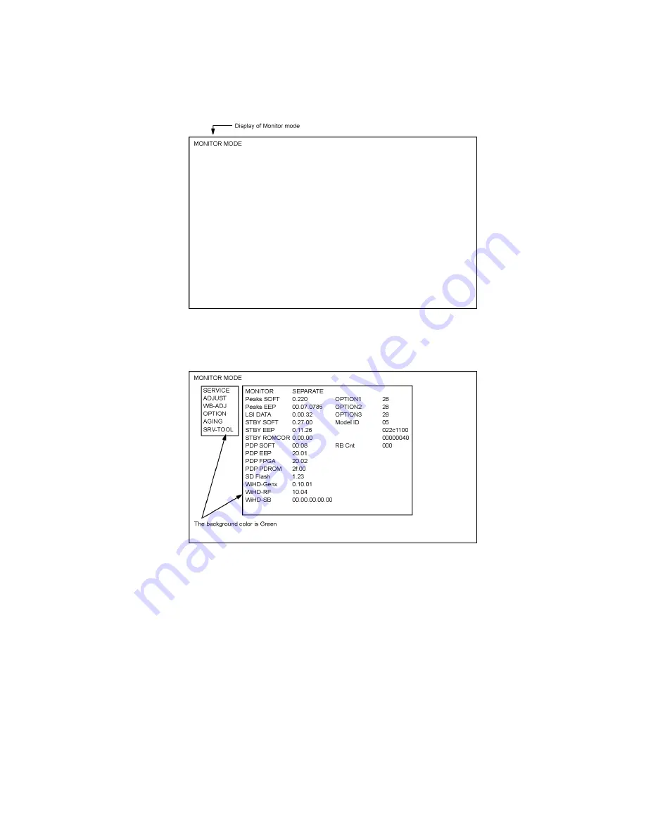
Monitor mode
Monitor mode use the RF remote control.
5.1.2.1.
How to access
1. Select [Monitor] in Service Mode of Tuner box.
2. Press [OK] button on the RF remote control.
5.1.2.2.
How to enter into Service Mode of the Display unit
While pressing [VOLUME ( - )] button of the Display unit, press [INFO] button of the RF remote control three times within 2 seconds.
Service mode of the Display unit sees section 5.2.
Summary of Contents for TU-Z100U
Page 24: ...24 6 4 No Picture ...
Page 44: ...44 9 1 4 Adjustment Volume Location 9 1 5 Test Point Location ...
Page 56: ...56 11 3 Wiring Tuner box 2 ...
Page 57: ...57 11 4 Wiring Display unit 1 ...
Page 58: ...58 11 5 Wiring Display unit 2 ...
Page 59: ...59 11 6 Wiring Display unit 3 ...
Page 60: ...60 ...
Page 61: ...61 12 Schematic Diagram 12 1 Schematic Diagram Note ...
Page 148: ...148 ...
Page 150: ...150 14 1 2 Exploded view 2 Display unit 1 ...
Page 151: ...151 14 1 3 Exploded view 3 Display unit 2 ...
Page 152: ...152 14 1 4 Exploded view 4 Wireless unit Transmitter ...
Page 153: ...153 14 1 5 Exploded view 5 Wireless unit Recevier ...
Page 154: ...154 14 1 6 Packing 1 ...
Page 155: ...155 14 1 7 Packing 2 ...
Page 156: ...156 14 1 8 Packing 3 ...
Page 157: ...157 14 1 9 Packing 4 ...
Page 158: ...158 14 1 10 Packing 5 Pedestal ...
Page 159: ...159 14 1 11 Packing 6 ...
Page 160: ...160 14 1 12 Packing 7 ...
Page 161: ...161 14 1 13 Packing 8 ...
Page 168: ...168 14 2 Electrical Replacement Parts List 14 2 1 Replacement Parts List Notes ...
Page 222: ...Caution Sheet TRANSMISSION RECEIVER UNIT ...
Page 224: ...P FILTER Board SCREW THEL071J SCREW THEC108J SARCON SHEET TMKK362 SARCON SHEET TMKK362 ...
Page 227: ...4 Location of SARCON Sheet 260 mm 10 2 80 mm 3 1 100 mm 3 9 200 mm 7 8 Sarcon sheet ...


