ー 30 ー
ー 31 ー
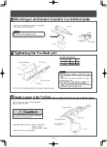
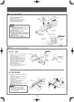
Mounting an end tension insulator to a terminal plate
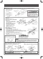
Tightening the Tro-Reel unit
Pull the Tro-Reel unit tight and tighten the end tension insulator nut snugly.
●
Length of coil spring
●
After completing installation, run the hoist or crane
ten or more times and reconfirm the spring tightening
length.
Failure to do so may cause poor collector arm contact or
separation from wires.
●
After installation, let the hoist and crane travel for
more than 10 times and recheck the tightness of
spring. If this job is not properly done, bad contact or
detailing of collector arm may occur.
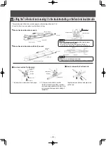
1.Insert the terminal plate into the groove of insulator.
2.Mount the cover to the insulator.
Cover
Special washer
Insulator
Insulator
Insert into the
groove.
Terminal plate
End tension insulator bracket
End tension insulator
Nut
bolt
(
M12
)
I-beam
L
Coil spring
Tro-Reel unit
10
℃
or lower
11
〜
40
℃
Ambient temperature
during installation
115mm
125mm
L
2254
1568
Tension
(N)
6
7
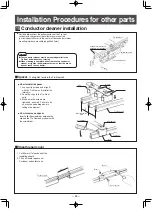
Feeding power to the Tro-Reel
Power can be fed from the line end via an end tension insulator.
Connect the power wire to the terminal plate
using a crimp-on terminal.
Applicable crimp-on terminals: _<50mm
2
(60A, 150A)
_<100mm
2
(200A)
_<150mm
2
or 100mm
2
×
(300A)
Crimp-on terminals are not included.
End tension insulator
Terminal plate
Cover
Crimp-on terminal
(not included)
Terminal screw
(
M-8
)
8
Terminal screws must be securely tightened.
Failure to do so may cause fire.
Caution
Notes
●
Be sure to mount the special washer.
Failure to do so may cause damage of the insulator.
Notes
●
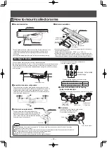
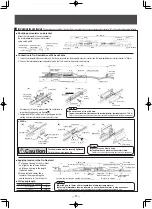
Set the distance from the bottom surface of the Tro-reel conductor to the
center ofthe collector arm mount rod (not included) to 95mm (in the
center of the conductor cleraner mounting tolerance movable range
95±20mm)
●
Arm must be attached parallel to the Tro-Reel unit without any twisting.
■
Standard installation
●
Two collector arms should be used together (tandem type) for circuit
separation and line swiching, and especially in applications in which it is
imperative that collector arms not be separated from wires. Tandem
collector arms cannot be used horizontally. For horizontal installations,
use a single-type collector arm.
■
Assembly in tandem configuration
●
Collector shoes should be replaced when they
partially wear down to the replacement indication line.
Please exchange the collector shoes ahead of time
when it will be worn out to the replacement indication
line by the time of the next check.
■
Collector shoe replacement
●
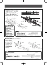
As shown in a figure,mounted collector arm support parts for transverse
on base of the collector arm.
Tightening torque of fixing screws
:
0.98 N
・
m
〜
1.32 N
・
m
●
Set the distance from the bottom surface of the Tro-reel conductor to the
center ofthe collector arm mount rod (not included) to 95mm (in the center
of the conductor cleraner mounting tolerance movable range 95±20mm)
■
Horizontal installation
Replacement line
Collector shoe
Bolt
Bolt
Bolt
Bolt
●
After installation, be sure that the hanger, the Tro-Reel unit and the collector arm are level. Failure to do so may
cause poor collector arm contact.
●
When you want to use the collector arms with centerring horizontally,please contact Panasonic electric Works,Ltd.
●
In a horizontal ways case, be sure to use the horizontal support parts.
Failure,there is a risk of derailment or loose arms collector.
●
Distance to the center of the collector arm from the center of the duct
Notes
Tro-Reel unit
Collector arm
Collector arm mount rod, 25
×
25mm
(not included)
95
±
20mm
(movable area)
Fixing screw
Base
Collector arm support
parts for transverse
95
±
20mm
Tro-Reel unit
Collector arm
Collector arm
mount rod
(not included)
(movable area)
How to mount collector arms
9
110mm
70mm
■
Horizontal installation with its opening
facing into tandem-type
■
Wire clamp
Give slack to a lead.(Lead is a fixed position,
430mm from the base of collector)
Do not affect a collector's run.
(M4×8
)
Push here.
430mm
When collector arm mount rod set up a reference
position,
the operating range from 70mm
〜
110mm of collector arm set up to be twisting.
Adjust the arm mount rod between the High-Tro-Reel unit to become 110mm
or less and 70mm or more at the center between hangers, and 70mm or more
at the bracket.
Lead
Collector arm
Collector arm mount rod
Fixing screw
Collector arm
support parts
for transverse
Collector arm
support parts
for transverse
Use range of movable
A
A
Distance to the center of the collector arm
from the center of the duct
Dimension A of permitted
movable range
Distance to the center of the collector arm
from the center of the duct
Give slack to a lead.
Cable clamp
Use the horizontal support parts
5mm
Not use the horizontal support parts 15mm
●
Mounting the horizontal support parts in both the collector arms


