background image

1

.2. Troubleshooting


Please take note of the following two points with regard to troubleshooting: 

1. Know-how of diagnosis upon occurrence of heavy troubles, e.g.  Set cannot be turned ON,  Set fails to start ,  No display on 

screen , etc. 

2. Explanation of each trouble, mainly symptom of trouble in operation. 
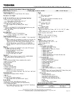
 

  Flow Chart 


NG

NO

YES

NG

NO

YES

NG

OK

OK

NO

YES

NG

OK

NG

OK

NO

YES

OK

OK

NG

START 

START 

Pay attention to the following points when in pursuit of the cause of a troubleshooting. 
1. Peripheral apparatus connected with the set should all be removed before operation check. 
2. Make sure that cables, boards, etc. are not coming off, and recheck the contact condition.   

Set cannot be supplied with current. 
Power lamp fails to light up. 

AC 

Adaptor/Battery 

Output voltage

Replace AC Adaptor/Battery

Return set-up utility setpoint to the state of  delivery from factory .

Make sure of contact of K/B connector in use.
Replace keyboard or main board. 

Replace main board.

Reinstall HDD. 
Replace main board. 

Power lamp 

check

Check contact condition of power input terminal. Replace if
defective. 
Check Power SW. Replace if defective. 

Inverter board

Replace inverter board. 
Check inverter cable continuity. Replace if defective 

Replace LCD back light.

BIOS operation 

check

Replace main board (Check fuse at power source). 

LCD unit 

check

Replace LCD unit.

Result of 

POST

Refer to POST 
error code table.

Replace main board. 

Main board 

check

Replace main board 

HDD access

Check HDD cable connection and continuity. 
Replace if defective. 
Replace HDD & Reinstall. 
Replace main board. 

Set-up utility 

starting 

Replace main board. 

Trouble

symptoms on some 

of CD

START 

END 

Dark display on screen. 
Screen fails to display. 

Failure in starting 

Not displayed properly on screen. 

Some or all keys cannot be input. 

CD CALL not practicable. 

Starts but operates unstably. 

Heavy trouble e.g., 

Set cannot be turned 

ON,  Set fails to start , 

No display on 

screen , etc. 

Each kind of 
trouble in 
operation. 


LCD back 

light lighting

NO

YES

Check if there are any flaws on CD media. Since 
flaws may appear on specific media, CD media 
can be defective.

7 / 20

Summary of Contents for Toughbook CF-74FCBCZBM

Page 1: ...ok Computer 2007 Matsushita Electric Industrial Co Ltd All rights reserved Unauthorized copying and distribution is a violation of law Model No CF 74FCBCZBM This is the Service Manual for the following areas M for U S A and Canada ...

Page 2: ...ECTRICAL SHOCK IF THE CUT OFF PLUG IS INSERTED INTO ANY 13 AMP SOCKET If a new plug is to be fitted please observe the wiring code as shown below If in any doubt please consult a qualified electrician Warning THIS APPLIANCE MUST BE EARTHED Important The wires in this mains lead are coloured in accordance with the following code Green and yellow Earth Blue Neutral Brown Live As the colours of the w...

Page 3: ...gned to be incorporated into a computer based system or unit which has an enclosing cover It should never be used as a stand alone drive Danger The serviceman should not remove the cover of drive unit and should not service because the drive unit is a non serviceable part Please check DANGER label on PD drive unit Unplug the AC power cord to the equipment before opening the top cover of the drive ...

Page 4: ...4 20 ...

Page 5: ...5 20 ...

Page 6: ...1 Diagnosis Procedure 1 1 Basic Procedures 6 20 ...

Page 7: ... main board Reinstall HDD Replace main board Power lamp check Check contact condition of power input terminal Replace if defective Check Power SW Replace if defective Inverter board Replace inverter board Check inverter cable continuity Replace if defective Replace LCD back light BIOS operation check Replace main board Check fuse at power source LCD unit check Replace LCD unit Result of POST Refer...

Page 8: ...splay of OK etc Error Diagnosis by Checking Beep Signal Sound The beep sound is as follows long sound about 0 4 sec short sound about 0 2 sec Length between sounds is about 0 1 sec Table of errors classified by beep sounds 1 long sound 2 3 4 Length of bar shows length of sound Diagnosis Beep signal sound Error message 1 long sound 2 BIOS ROM error BIOS ROM error RAM error Keyboard controller error...

Page 9: ...ror was detected 0232 Extended RAM Failed at offset nnnn Extended memory not working or not configured properly at offset nnnn 0250 System battery is dead Replace and run SETUP The CMOS clock battery indicator shows the battery is dead Replace the battery and run Setup to reconfigure the system 0251 System CMOS checksum bad Default configuration used System CMOS has been corrupted or modified inco...

Page 10: ...d bit See error 230 231 or 232 for offset address of the failure in System Extended or Shadow memory Invalid System Configuration Data Problem with NVRAM CMOS data I O device IRQ conflict I O device IRQ conflict error Operating System not found Operating system cannot be located on either drive A or drive C Enter Setup and see if fixed disk and drive A are properly identified Parity Check 1 nnnn P...

Page 11: ...e test of all devices begins automatically by PC Diagnostic utility s starting It is a test which the customer who bought PC can execute As for HDD the enhancing test is also possible A flat pad does not work for a while after starting PC Diagnostic utility The movement of a flat pad might become abnormal If after RAM begins from the CPU System test a flat pad will be operated in about 30 seconds ...

Page 12: ... the left of the icon The diagnosis result of the device greens at the left of the icon when it is normal and becomes red when abnormal Please click while diagnosing when being stop on the way by the time the test of all devices ends Please click when you restart PC Diagnostic utility Each device is tested from the beginning and it is not possible to restart on the way When the test of all devices...

Page 13: ...a difference from HDD according to the performance of the drive occasionally 2 3 The content of the setup is returned to the setting of the user Standard at test time All devices other than RAM and HDD RAM standard test HDD standard test HDD enhancing test 60GB about 1 minute 1 2 minutes 2 3 minutes about 40 minutes To test only a specific device Test and Do not test of each device can be selected...

Page 14: ...ng be tween the USB controller and the connector by confirming the connection of the USB equipment connected with the USB connector Sound USB It is confirmed not to find abnormality in the USB controller Mainboard Connector It is confirmed not to find ab normality in the wiring be tween the controller and the connector by connecting to HUB with LAN cable LAN It is confirmed not to find abnormality...

Page 15: ...erial Port 7 It is confirmed not to find abnormality of Super I O UART function This test cannot find lack of wiring between Super I O and Serial Connector It is confirmed not to find abnormality in the wiring between Super I O and Serial Connector This test cannot find failure of cable characteristic and device problems Main board Super I O Serial Connector Parallel Port 8 It is confirmed not to ...

Page 16: ...1 K18 DFHM0386ZA 0 DFHM0386ZB 0 IO COVER PLATE 1 K20 DFHM0390ZA 0 DFHM0390ZB 0 PC COVER PLATE 1 K60 DFQT9981ZA CENTRINO DUO LABEL 1 0 K86 DFMC0855ZA DFMC0855ZA USB GASKET 4 3 K93 DFHR3C64ZB NO SMART CARD SHEET 1 0 K94 DFHR3C99ZA NO SC CUSHION 1 0 K99 DFHG1599ZA LCD DUMPER A 1 0 K100 DFHR3D53ZB SLIDE SHEET 1 0 K206 DFMX0778ZA DFMX0778ZA SHEET 4 3 N9 DFHE5025XA DFHE5025XA SCREW 43 41 K1006 DFHE1024Z...

Page 17: ... N2 N4 K27 N2 N4 E3 K35 E19 E37 K30 K21 N9 K19 K50 E30 K25 K42 E31 K50 E30 K24 K42 E31 K206 N6 K23 K206 K71 K71 K78 K69 K78 K72 K58 K59 K47 Screw tightening torque 0 1 0 01 N m 1 0 0 1 kgf cm 0 2 0 02 N m 2 0 0 2 kgf cm 0 4 0 02 N m 4 0 0 2 kgf cm 1 2 0 1 N m 12 0 1 0 kgf cm 0 8 0 1 N m 8 0 1 0 kgf cm B D C C F A D B D B B N9 B N9 B N9 B N13 B N9 B C N9 B B N5 B N9 B N9 B N9 B N12 A F F N9 B N20 B...

Page 18: ...1 K91 K84 K96 K57 B N5 B N5 B N7 B N7 B N7 B N9 B N8 B N8 B N9 B N9 B N3 B N1 K55 Screw tightening torque 0 2 0 02 N m 2 0 0 2 kgf cm 0 13 0 01 N m 1 3 0 1 kgf cm B E K15 K12 K20 K88 K90 K2 N9 B K18 K11 K95 K87 K89 K95 K85 K13 K14 K97 N9 N9 K8 K34 K36 K49 K17 K52 K101 N9 N9 E10 E1 E38 E13 E9 B N9 B N9 B N9 B N9 B N9 K92 B B B B B N9 K1011 K1013 18 20 ...

Page 19: ... 1 0 kgf cm 0 375 0 025 N m 3 75 0 25 kgf cm K205 K210 6 K211 K210 2 K212 K26 K16 K210 1 K210 a K204 K204 K208 E26 K202 E25 K201 K206 E14 E14 1 K210 3 K3 K4 K210 4 A N18 B N16 G N15 G N15 A N17 F N6 F N6 E15 E15 1 A B N18 N9 F K210 5 F K210 5 A B K207 K207 K207 K209 K203 K22 E23 E6 E24 K207 K207 F G E22 19 20 ...

Page 20: ...CF 74FCBCZBM E22 6 6 E22 6 3 E22 1 E22 2 E22 3 E22 4 E22 4 E22 4 E22 4 E22 5 E22 E22 6 2 E22 6 4 E22 6 4 E22 6 E22 6 1 1 E22 6 1 E22 6 5 E22 6 5 a 20 20 ...

Reviews: