22
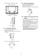
4. Remove the spacers and spacer rings (
×
6 ).
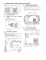
7.17. Remove the S-Board
1. Remove the Cabinet assy. (See section 7.16.)
2. Disconnect the connector (S2).
3. Remove the screws (
×
2
) and remove the S-Board
metal frame.
4. Remove the screws (
×
2
) and remove the S-Board.
7.18. Remove the K-Board
1. Remove the Cabinet assy. (See section 7.16.)
2. Remove the S-Board. (See section 7.17.)
3. Remove the screws (
×
2 ).
4. Disconnect the connector (K1) and Remove the K-Board.
7.19. Replace the plasma panel (fin-
ished)
1. Place the new plasma panel (finished) on the flat surface
of the table (covered by a soft cloth), with the plasma
panel surface facing downward.
2. Attach the C1-Board and the C2-Board, connect the flexi-
ble cables (
×
8) from the plasma panel to the C1-Board
and the C2-Board, and fit the flexible cable holders.
3. Attach the Hooks (left, right) and fit the stand brackets (L,
R) to the new plasma panel.
4. Place the plasma panel section on the servicing stand.
5. Attach the cabinet assy and each P.C.Board and so on, to
the new plasma panel.
*When fitting the cabinet assy, be careful not to allow
any debris, dust or handling residue to remain
between the front glass and plasma panel.
Summary of Contents for THC42HD18A - 42" PLASMA TV
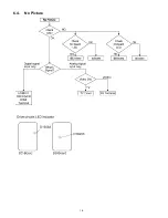
Page 16: ...16 6 4 No Picture ...
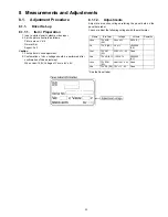
Page 25: ...25 8 1 4 Adjustment Volume Location 8 1 5 Test Point Location ...
Page 27: ...27 ...
Page 28: ...28 ...
Page 34: ...34 ...
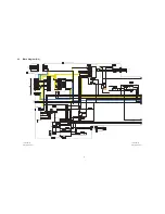
Page 36: ...36 10 3 Wiring 2 ...
Page 37: ...37 11 Schematic Diagram 11 1 Schematic Diagram Note ...
Page 90: ...90 13 1 2 Accessories ...
Page 91: ...91 13 1 3 Mechanical Replacement Parts List ...
Page 94: ...94 13 2 Electrical Replacement Parts List 13 2 1 Replacement Parts List Notes ...


