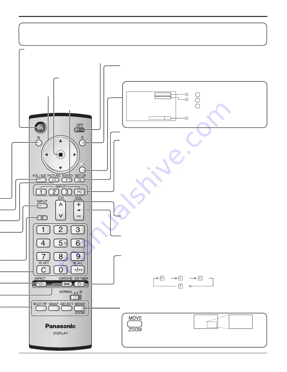
background image

15

Basic Controls

OFF  TIMER

90

1

2

3

P C

N O R M A L

Standby (ON / OFF) button

The Plasma Display must first be plugged into the wall outlet and turned on at the power switch (see page 12).
Press ON to turn the Plasma Display On, from Standby mode. Press OFF to turn the Plasma Display Off 
to Standby mode.

SET UP button

 (see page 16, 17)

DIRECT INPUT buttons

Press the INPUT “1”, “2”, “3” or “PC” input mode selection button to 
select the INPUT mode.
This button is used to switch directly to INPUT mode.
These buttons can only display the slot which is installed. If you press the button 
whose slot is not installed, it automatically displays the current input signal.
When a dual input terminal board is attached, A or B is displayed 
depending on the selected input signal. (Ex. INPUT1A, INPUT1B)

Note:

Image retention (image lag) may occur on the plasma display panel when 
a still picture is kept on the panel for an extended period. The function that 
darkens the screen slightly is activated to prevent image retention (see 
page 42), this function is not the perfect solution to image retention.

Channel Adjustment 

You can use this button when U/V Tuner Board with MATE I/F is installed 
(optional accessories). Refer to each Board's Operating Instruction for detail.

Volume Adjustment

Press the Volume Up “+” or Down “–” button to increase or decrease 
the sound volume level.

OFF TIMER button

The Plasma Display can be preset to switch to stand-by after a fixed 
period. The setting changes to 30 minutes, 60 minutes, 90 minutes and 
0 minutes (off timer cancelled) each time the button is pressed.

When three minutes remain, “OFF TIMER 3” will flash.
The off timer is cancelled if a power interruption occurs.

Digital Zoom

 (see page 25)

Status button

Press the “Status” button to display the current system status.

Press to access 
Digital Zoom.

This displays an enlargement of the designated part of the displayed 
image. 

ACTION button

Press to make
selections.

SOUND button

 (see page 24)

R button

 (see page 17) 

Press the R button to return to previous menu screen.

30

60

0

90

POSITION 

buttons

1

  Input label

2

  Aspect mode (see page 18)

3

  Off timer

  The off timer indicator is 

displayed only when the off 
timer has been set.

The remote control is not included with this set. Available for purchase separately.

Object model : EUR7636070R

Summary of Contents for TH37PR10U - 37" PLASMA TELEVISION

Page 1: ...Model No N mero de modelo TQB2AA0801 1 Antes de conectar utilizar o ajustar este producto lea completamente este manual de instrucciones y gu rdelo para consultarlo en el futuro en caso de ser necesa...

Page 2: ...appliance WARNING To prevent damage which may result in fire or shock hazard do not expose this apparatus to rain or moisture Do not place containers with water flower vase cups cosmetics etc above t...

Page 3: ...nt of the obsolete outlet 10 Protect the power cord from being walked on or pinched particularly at plugs convenience receptacles and the point where they exit from the apparatus 11 Only use attachmen...

Page 4: ...input signal 13 Selecting the On Screen Menu Language 13 Basic Controls 14 On Screen Menu Displays 16 ASPECT Controls 18 Adjusting POS SIZE 19 MULTI PIP 20 Advanced PIP 21 PICTURE Adjustments 22 ADVAN...

Page 5: ...is device must accept any interference received including interference that may cause undesired operation FCC CAUTION To assure continued compliance use only shielded interface cables when connecting...

Page 6: ...ventilation holes of the Plasma Display Top of the Plasma Display is usually very hot due to the high temperature of exhaust air being released through the ventilation holes Burns or personal injuries...

Page 7: ...l optional accessory leave a space of 3 15 16 10 cm or more at the top left and right 2 3 8 6 cm or more at the bottom and 2 3 4 7 cm or more at the rear If using some other setting up method leave a...

Page 8: ...ies Supplied Check that you have the Accessories and items shown Operating Instruction book AC cord The remote control is not included with this set Available for purchase separately Object model EUR7...

Page 9: ...rough the locking block as shown in the figure While ensuring there is sufficient slack in cables to minimize stress especially in the power cord firmly bind all cables with the supplied fixing band T...

Page 10: ...computer at the time of connection Some PC models cannot be connected to the set There is no need to use an adapter for computers with DOS V compatible Mini D sub 15P terminal The computer shown in t...

Page 11: ...smitted be sure to wait for the response for the first command to come from this unit before sending the next command If an incorrect command is sent by mistake this unit will send an ER401 command ba...

Page 12: ...During operation of the power management function the power indicator turns orange in the power off state Power Indicator Remote Control Sensor Fix the AC cord plug securely to the Plasma Display wit...

Page 13: ...languages Select the input signals to be connected by installing the optional Terminal Boards Press to select the input signal to be played back from the equipment which has been connected to the Plas...

Page 14: ...ch time the MENU button is pressed the menu screen will switch see page 16 Power Indicator The Power Indicator will light Power OFF Indicator not illuminated The unit will still consume some power as...

Page 15: ...t solution to image retention Channel Adjustment You can use this button when U V Tuner Board with MATE I F is installed optional accessories Refer to each Board s Operating Instruction for detail Vol...

Page 16: ...FF STANDBY SAVE OFF POWER MANAGEMENT OFF AUTO POWER OFF OFF OSD LANGUAGE ENGLISH US COMPONENT RGB IN SELECT RGB INPUT LABEL SIGNAL POWER SAVE SET UP 2 2 SET UP SCREENSAVER MULTI DISPLAY SETUP SET UP T...

Page 17: ...CREENSAVER START FUNCTION MODE WOBBLING PEAK LIMIT FINISH TIME START TIME WHITE BAR SCROLL TIME OF DAY 6 15 12 30 OFF OFF SIDE BAR ADJUST BRIGHT PRESENT TIME OF DAY 15 00 SCREENSAVER START FUNCTION MO...

Page 18: ...e to change unexpectedly When viewing such programs it is recommended that the ASPECT be set to NORMAL If adjusting the PICTURE V POS V SIZE in PanasonicAUTO with FULL mode the adjustment is not memor...

Page 19: ...nals are memorized for each frequency If a Cue or Rew signal from a VCR or DVD player is received the picture position will shift up or down This picture position movement cannot be controlled by the...

Page 20: ...nd output is from the picture which is selected in Audio OUT PIP See page 24 In 2 screen display the same input mode cannot be selected for the main picture and sub picture The main picture and sub pi...

Page 21: ...sions of the sub pictures these sub pictures cannot be shown in detail Computer screen picture is displayed in a simplified format and it may not be possible to discern details on them satisfactorily...

Page 22: ...to something else adjust using the items in the PICTURE menu see next page PICTURE Adjustments 1 2 ADVANCED SETTINGS ON Enables fine picture adjustment at a professional level see next page ADVANCED S...

Page 23: ...nes SHARPNESS Less More Adjusts picture sharpness Item Effect Details BLACK EXTENSION Less More Adjusts the dark shades of the image in gradation INPUT LEVEL Less More Adjustment of parts which are ex...

Page 24: ...the sound 2 Select to adjust each item Useful when answering the phone or receiving unexpected visitors Press this button to mute the sound Press again to reactivate sound Sound is also reactivated wh...

Page 25: ...lowing operation state Multi viewer Picture in Picture Picture out Picture Picture and Picture operation see page 20 While Digital Zoom is in operation Adjusting POS SIZE cannot be used Select the mag...

Page 26: ...Then set POWER ON TIME POWER OFF TIME Press to display the SET UP menu Press to select SET UP TIMER or PRESENT TIME SETUP Press to display the SET UP TIMER screen or PRESENT TIME SETUP screen Display...

Page 27: ...TIMER Press to select POWER ON TIME POWER OFF TIME Press to set up POWER ON TIME POWER OFF TIME button Forward button Back Notes Pressing or button once changes POWER ON TIME POWER OFF TIME 1minute Pr...

Page 28: ...SCROLL selection 2 3 1 4 Press to display the SET UP menu Press to select the SCREENSAVER Press to select the SCREENSAVER screen Press to select the FUNCTION Press to select the desired function WHIT...

Page 29: ...RATION SHOW DURATION WHITE BAR SCROLL INTERVAL 12 00 3 00 OFF OFF SIDE BAR ADJUST BRIGHT PRESENT TIME OF DAY 15 00 Setup of SCREENSAVER Time After selecting TIME OF DAY or INTERVAL the relevant Time S...

Page 30: ...of the display field To reduce the risk of such an image retention change the brightness of the side bars Display the SCREENSAVER screen Refer to the previous page operation guide steps 1 and 2 Notes...

Page 31: ...is no signal When this is set to On the power supply of the unit goes Off 10 minutes after the input signals stop This function is effective for input signals except input from PC Mini D sub terminal...

Page 32: ...COMPONENT RGB IN SELECT Select to match the signals from the source connected to the COMPONENT RGB input terminals Y PB PR signals COMPONENT R G B HD VD signals RGB Press to display the SET UP menu Pr...

Page 33: ...t from adjust mode 3 2 PULLDOWN When ON the display attempts to reproduce a more natural interpretation of sources such as movie pictures which are recorded at 24 frames per second If the picture is n...

Page 34: ...just mode SYNC Setting RGB sync signal Confirm that the input is set to RGB INPUT this setting is valid only for RGB INPUT signal AUTO The H and V sync or synchronized signal are automatically selecte...

Page 35: ...ommand Timer Sets Weekly Command Timer see page 39 Onscreen display On Off On Displays all the following on screen Power on display Input signal switch display No signal display Mute and the remaining...

Page 36: ...tch operation Notes Only the adjusted signal is displayed see page 13 Signal can be displayed when the Terminal board is installed Input switch can be used when this is set to Off In two screen displa...

Page 37: ...f On Sets the panel ID Control Off Disables external control by the ID On Enables the external control by the ID Display size Off On Adjusts the image display size on screen Off Sets the normal image...

Page 38: ...n Note This mode is unavailable Rotate Off On Off Does not rotate the image On Rotates the image 180 degrees Serial Slot Select Slot1 Slot2 Slot3 Selects the slot which communicates serial Note The se...

Page 39: ...OM AVL 10 07 08 1 Program Program number Options Adjustments Weekly Command Timer You can set 7 day timer programming by setting time and command Note Before setting Weekly Command Timer set PRESENT T...

Page 40: ...lect Command No Press to select a command number 6 Press to select Time Command Press to set each item Time Set the time to execute a command program Pressing or button once changes Time 1 minute Pres...

Page 41: ...u Press to select OSD LANGUAGE Press and hold till the SHIPPING menu is displayed Press to select YES Press to confirm from the unit 1 Press the MENU button till the Setup menu is displayed 2 Press th...

Page 42: ...ative of malfunctioning This Plasma Display uses special image processing Hence a slight time lag may occur between image and audio depending on the type of input signal However this is not a malfunct...

Page 43: ...6 56 25 36 0 21 800 600 60 Hz 37 88 60 32 40 0 22 800 600 72 Hz 48 08 72 19 50 0 23 800 600 75 Hz 46 88 75 00 49 5 24 800 600 85 Hz 53 67 85 06 56 25 25 1 024 768 60 Hz 48 36 60 00 65 0 26 1 024 768 7...

Page 44: ...ture mode Picture in Picture 36 DWA POP Dual Picture mode Picture out Picture 37 DWA SWP Swap main picture and sub picture when PIP mode 38 DWA TWN Dual Picture mode Picture and Picture 39 IMS PC1 Inp...

Page 45: ...A compressed Horizontal scanning frequency 15 110 kHz Vertical scanning frequency 48 120 Hz VGA SVGA XGA SXGA UXGA compressed Horizontal scanning frequency 15 110 kHz Vertical scanning frequency 48 12...

Page 46: ...R CONSEQUENTIAL DAMAGES INCLUDING WITHOUT LIMITION DAMAGE TO DISCS RESULTING FROM THE USE OF THIS PRODUCT OR ARISING OUT OF ANY BREACH OF THE WARRANTY ALL EXPRESS AND IMPLIED WARRANTIES INCLUDING THE...

Page 47: ...coverage period Proof of product purchase is a condition of warranty service The owner must produce the product purchase receipt or other satisfactory evidence of date of original purchase This warran...

Page 48: ...llas Region 6226 Abington Way Houston TX 77008 713 802 2726 No CA Northwest Region 5870 Stone Ridge 3 Pleasanton CA 925 416 5108 Government Marketing Department 52 West Gude Drive Rockville MD 20850 3...

Reviews: