Panasonic TH32LR11UK - 32

40

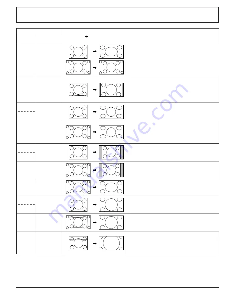
List of Aspect Modes

Aspect mode

Picture

 Enlarged screen

Description

All Aspect: 
On

Factory setting
All Aspect: Off

16:9

FULL

The display of the pictures fi lls the screen.
In the case of SD signals, pictures with a 4:3 aspect ratio are 
enlarged horizontally, and displayed. This mode is suited to 
displaying anamorphic pictures with a 16:9 aspect ratio.

14:9

Letterbox pictures with a 14:9 aspect ratio are enlarged 
vertically and horizontally so that their display fi lls the 
screen vertically and is slightly smaller than the screen 
horizontally. The top and bottom edges of the pictures are 
cut off. Side panels are displayed at the left and right edges 
of the screen.

Just

JUST

Pictures with a 4:3 aspect ratio are enlarged horizontally 
so that the picture distortion is minimized. The display of 
the areas around the left and right edges of the screen is 
slightly elongated.

Just1

Just2

JUST

Pictures with a 4:3 aspect ratio are enlarged horizontally 
so that the picture distortion is minimized. The left and right 
edges of the pictures are cut off. The display of the areas 
around the left and right edges of the screen is slightly 
elongated.

4:3

4:3

Pictures with a 4:3 aspect ratio are displayed with their 
original aspect ratio. Side panels are displayed at the left 
and right edges of the screen.

4:3 (1)

4:3 (2)

4:3

Pictures with a 4:3 aspect ratio are displayed with their 
original aspect ratio. The left and right edges of the pictures 
are masked by side panels.

4:3 Full

H-FILL

Pictures with a 4:3 aspect ratio are enlarged horizontally so 
that their display fi lls the screen. The left and right edges of 
the pictures are cut off.

Zoom

ZOOM

Letterbox pictures with a 16:9 aspect ratio are enlarged 
vertically and horizontally so that their display fi lls the screen. 
The top and bottom edges of the pictures are cut off.

Zoom1

Zoom2

ZOOM

Letterbox pictures with a 16:9 aspect ratio are enlarged 
vertically and horizontally so that their display fi lls the screen. 
The top and bottom edges as well as the left and right edges 
of the pictures are cut off.

Zoom3

Letterbox pictures with a 2.35:1 aspect ratio are enlarged 
vertically and horizontally so that their display fi lls the screen 
vertically and is slightly larger than the screen horizontally. 
The top and bottom edges as well as the left and right edges 
of the pictures are cut off.

Summary of Contents for TH32LR11UK - 32" LCD TV

Page 1: ...g this product please read these instructions completely Please keep this manual for future reference The illustration shown is an image TH 32LR11UK TH 32LR11UH Model No English Operating Instructions...

Page 2: ...wer analog TV broadcasting in the United States will end as required by law on February 17 2009 after which full power TV broadcasts will be digital only If this device is used after that date to reco...

Page 3: ...nt of the obsolete outlet 10 Protect the power cord from being walked on or pinched particularly at plugs convenience receptacles and the point where they exit from the apparatus 11 Only use attachmen...

Page 4: ...nals connection 11 Power ON OFF 12 Initial selections 13 Selecting the input signal 13 Selecting the On Screen Menu Language 13 Basic Controls 14 ASPECT Controls 16 MULTI PIP 17 Advanced PIP 18 Digita...

Page 5: ...his device may not cause harmful interference and 2 this device must accept any interference received including interference that may cause undesired operation FCC CAUTION To assure continued complian...

Page 6: ...ch might damage the insulation and cause re Unplug the cord from the wall outlet and clean it with a dry cloth This Display radiates infrared rays therefore it may affect other infrared communication...

Page 7: ...rting the unit with its display panel facing upright or downward may cause damage to the internal circuitry When using the pedestal leave a space of 3 15 16 10 cm or more at the top left and right and...

Page 8: ...istance for viewing Avoid placing it where sunlight or other bright light including re ections will fall on the screen Use of some types of uorescent lighting can reduce remote control transmitter ran...

Page 9: ...ews B Pull out the pedestal B A A Foam mat or thick soft cloth WARNING Failure to use a Panasonic bracket or choosing to mount the unit yourself will be done at the risk of the consumer Any damage res...

Page 10: ...D sub 15P terminal The computer shown in the illustration is for example purposes only Additional equipment and cables shown are not supplied with this set Do not set the horizontal and vertical scan...

Page 11: ...1 P2 P3 P4 P5 ETX Notes If multiple commands are transmitted be sure to wait for the response for the rst command to come from this unit before sending the next command If an incorrect command is sent...

Page 12: ...the Display off Power Indicator Red standby Press the button on the remote control to turn the Display on Power Indicator Green Turn the power to the Display off by pressing the POWER switch on the u...

Page 13: ...optional Terminal Boards Press to select the input signal to be played back from the equipment which has been connected to the Display Input signals will change as follows Notes Selecting is also pos...

Page 14: ...wer Indicator The Power Indicator will light Power OFF Indicator not illuminated The unit will still consume some power as long as the power cord is still inserted into the wall outlet Standby Red Pow...

Page 15: ...lume Up or Down button to increase or decrease the sound volume level R button see page 20 Press the R button to return to previous menu screen OFF TIMER button The Display can be preset to switch to...

Page 16: ...31 For a 4 3 image The aspect mode changes each time the ENTER button is pressed During MULTI PIP Operations Picture and Picture Picture in Picture 4 3 FULL Others Aspect switching is not possible fr...

Page 17: ...o move the sub picture Each time the location of the sub picture will be moved Notes This button is effective only in the picture in picture The sub picture may be hidden by the on screen display depe...

Page 18: ...ending on the 2 picture display mode Due to the small dimensions of the sub pictures these sub pictures cannot be shown in detail Computer screen picture is displayed in a simpli ed format and it may...

Page 19: ...e in the following operation state Multi viewer Picture in Picture Picture out Picture Picture and Picture operation see page 17 While Digital Zoom is in operation Adjusting POS SIZE cannot be used Se...

Page 20: ...AY 0 00 0 00 SET UP TIMER POWER OFF FUNCTION POWER OFF TIME POWER ON TIME POWER ON FUNCTION OFF OFF PRESENT TIME OF DAY 99 99 1 2 PICTURE NORMAL NORMALIZE STANDARD 25 0 0 0 5 BRIGHTNESS SHARPNESS PICT...

Page 21: ...When exiting the mode the screen will return to a former adjustment While the POS SIZE display is active if either the N button on the remote control is pressed at any time or the ACTION button is pre...

Page 22: ...justments 1 ADVANCED SETTINGS ON Enables ne picture adjustment at a professional level see next page ADVANCED SETTINGS OFF Displays images with settings of the PICTURE menu Press to enter Advanced Set...

Page 23: ...ent values are returned to the factory settings Helpful Hint NORMALIZE Normalization Item Effect Adjustments BACKLIGHT Darker Brighter Adjusts luminance of the back light PICTURE Less More Adjusts the...

Page 24: ...button on the remote control is pressed at any time or the ACTION button is pressed during NORMALIZE then all adjustment values are returned to the factory settings Helpful Hint NORMALIZE Normalizatio...

Page 25: ...nce changes PRESENT TIME OF DAY 1 minute Pressing or button continuously changes PRESENT TIME OF DAY by 15 minutes Press to select SET Press to store PRESENT TIME SETUP Notes SET cannot be selected un...

Page 26: ...display eld To reduce the risk of such an image retention illuminate the side bars Notes To reduce the occurrence of image retention set the SIDE BAR ADJUST to BRIGHT The side bar may ash alternate bl...

Page 27: ...automatically When no pictures HD VD sync signals are detected for 30 or so seconds during PC IN signal input Power is turned off standby the power indicator lights up orange When pictures HD VD sync...

Page 28: ...al Terminal Board connected to Slot 1 Slot 2 and Slot 3 the Input label will depend on each Optional Terminal Board INPUT LABELS for Slot 1 Slot 2 Slot 3 and Mini D sub Slot1 Input INPUT1 VIDEO1 COMPO...

Page 29: ...ET UP menu Press to select the COMPONENT RGB IN SELECT Press to select the desired mode COMPONENT RGB Press to exit from adjust mode Notes Selection may not be possible depending on which optional boa...

Page 30: ...63 98 60 02 SIGNAL FORMAT 1280 1024 60 RGB 3 2 PULLDOWN XGA MODE NOISE REDUCTION OFF AUTO OFF 1024 768 3D Y C FILTER NTSC ON 30 Press to select the menu to adjust Press to adjust the menu Press to exi...

Page 31: ...125 1080 60i signal input during COMPONENT input signal Mode Function COLOR SYSTEM Set the color system to match the input signal When selecting AUTO the color system is automatically selected from NT...

Page 32: ...MPEG videos BLOCK NR Reduces block noise when playing MPEG videos Notes NOISE REDUCTION cannot be adjusted while a PC signal is being applied BLOCK NR cannot be adjusted while a HD signal is being ap...

Page 33: ...UTO The H and V sync or synchronized signal are automatically selected If both input it is selected the H and V sync ON G Uses a synchronized signal on the Video G signal which is input from the G con...

Page 34: ...nal board is attached A or B is displayed depending on the selected input signal Ex INPUT1A INPUT1B Initial VOL level Press button to adjust the volume when the unit is turned on Off On Off Sets norma...

Page 35: ...hen INPUT lock is On you cannot use all the two screen display functions buttons are unavailable during Advanced PIP mode operation Off timer function Enable Enables the Off timer function Disable Dis...

Page 36: ...to the board Clock Display Off Not display the clock On Display the clock The clock is displayed at the lower left of the screen when button is pressed 10 00 Note When PRESENT TIME SETUP is not set t...

Page 37: ...ts Weekly Command Timer You can set 7 day timer programming by setting time and command Note Before setting Weekly Command Timer set PRESENT TIME SETUP see page 25 Press to select Function Press to se...

Page 38: ...TER button till the SHIPPING menu is displayed 4 Press the Volume Up or Down button to select YES 5 Press the ENTER button and wait for 10 sec Note Press the R button to return to SET UP menu when SHI...

Page 39: ...unction When using a video software program such as a cinema size program with a screen wider than one in the 16 9 mode blank areas separate from the images are formed at the top and bottom of the scr...

Page 40: ...he areas around the left and right edges of the screen is slightly elongated 4 3 4 3 Pictures with a 4 3 aspect ratio are displayed with their original aspect ratio Side panels are displayed at the le...

Page 41: ...1 080 30p 33 75 30 00 74 25 1 13 1 125 1 080 25p 28 13 25 00 74 25 1 14 1 125 1 080 24p 27 00 24 00 74 25 1 15 1 250 1 080 50i 31 25 50 00 74 25 3 16 640 400 70 Hz 31 46 70 07 25 17 17 640 480 60 Hz...

Page 42: ...ion of the sub picture upper right 35 DWA PIP Dual Picture mode Picture in Picture 36 DWA POP Dual Picture mode Picture out Picture 37 DWA SWP Swap main picture and sub picture when PIP mode 38 DWA TW...

Page 43: ...frequency 15 110 kHz Vertical scanning frequency 48 120 Hz Connection terminals PC IN HIGH DENSITY MINI D SUB 15PIN Y or G with sync 1 0 Vp p 75 Y or G without sync 0 7 Vp p 75 B PB CB 0 7 Vp p 75 R...

Page 44: ...A 925 416 5108 Government Marketing Department 52 West Gude Drive Rockville MD 20850 301 738 3840 Panasonic Canada Inc 5770 Ambler Drive Mississauga Ontario L4W 2T3 Customer s Record The model number...

Reviews: