Panasonic TH103VX200U - 103

Notes:

•  To use a DHCP server, make sure the DHCP server 

is started.

•  During a DHCP server is used, IP ADDRESS, 

SUBNET MASK, and GATEWAY values cannot be 
entered.

•  When the set values are changed properly, 

“NETWORK SETTING CHANGED.” message and 
the changed set items are displayed.
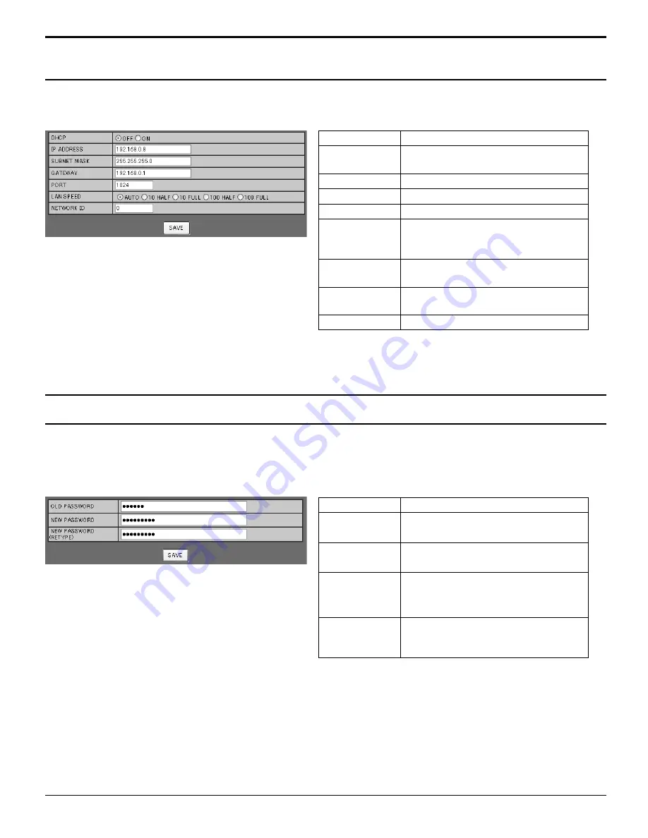
Item

Details

DHCP

Set to ON when a DHCP server is 
used, or OFF when it is not used.

IP ADDRESS

Enter an IP address.

SUBNET MASK Enter a subnet mask.
GATEWAY

Enter a gateway address.

PORT

Enter the port number used for 
command control. The available 
setting range is 1024 - 65535.

LAN SPEED

Set the connection speed of the LAN 
environment.

NETWORK ID

Set the ID to identify this unit. The 
available setting range is 0 - 99.

SAVE

Save the each set value.

Notes:

•  The default password is “Panasonic”.
•  Up to 32 alphanumeric characters can be used for a 

password.

•  When the password is changed properly, “Password 

has changed.” message is displayed.

Item

Details

OLD 
PASSWORD

Enter the old password.

NEW 
PASSWORD

Enter the new password.

NEW 
PASSWORD
(RETYPE)

Enter the password entered in “NEW 
PASSWORD” for con

fi

 rmation.

SAVE

Save the new password. The 
con

fi

 rmation screen is displayed.  

Click OK to change the password.

Click NETWORK SETTING from the menu. Various settings of a network can be set. For the details of the setting 
items, please check NETWORK SETUP under the SET UP of the unit. (see page 55)

Click CHANGE PASSWORD from the menu. Password to access the Web browser control can be set. When 
the password is changed in this screen, the password used for command control and the PJLink™ security 
authentication is also changed.

NETWORK SETTING (Network Setup Screen)

Password Setting (Password Setup Screen)

Using Web Browser Control

62

Summary of Contents for TH103VX200U - 103" FHD PLASMA TV

Page 1: ...VX200U Model No Operating Instructions High Definition Plasma Display English Before connecting operating or adjusting this product please read these instructions completely Please keep this manual fo...

Page 2: ...O NOT OPEN WARNING To prevent damage which may result in fire or shock hazard do not expose this apparatus to rain or moisture Do not place containers with water flower vase cups cosmetics etc above t...

Page 3: ...nt of the obsolete outlet 10 Protect the power cord from being walked on or pinched particularly at plugs convenience receptacles and the point where they exit from the apparatus 11 Only use attachmen...

Page 4: ...ages 25 Troubleshooting for 3D Eyewear 26 Table of images that can be seen for each 3D Picture Format and the source image format 26 On Screen Menu Displays 27 Adjusting POS SIZE 28 PICTURE Adjustment...

Page 5: ...that may cause undesired operation FCC CAUTION To assure continued compliance follow the attached installation instructions and use only shielded interface cables when connecting to computer or periph...

Page 6: ...ed for an extended period as this can cause a permanent image retention to remain on the Plasma Display Examples of still pictures include logos video games computer images teletext and images display...

Page 7: ...and 8 0 20 cm or more at the rear and also keep the space between the bottom of the display and the floor surface If using some other setting up method follow the manual of it If there is no specific...

Page 8: ...g Someone in authority should responsibly convey the precautions for use of the 3D Eyewear to the user 3D Eyewear Do not drop exert pressure on or step on the 3D Eyewear Always store the 3D Eyewear in...

Page 9: ...n to avoid it Do not use the 3D Eyewear at a distance less than the recommended distance View from at least the recommended distance 3 times the effective height of the screen TH 85VX200U 126 0 3 2 m...

Page 10: ...ge short circuit disassemble heat or burn used batteries 5 Battery replacement is necessary when the remote control acts sporadically or stops operating the Plasma Display 6 Do not burn or breakup bat...

Page 11: ...main unit No AC cord needs to be connected Pass the attached cable fixing band through the clip as shown in the figure To secure cables connected to Terminals wrap the cable fixing band around them t...

Page 12: ...e it separately Cable fixing bands Secure any excess cables with bands as required Pass the attached cable fixing band through the clip as shown in the figure To tighten To loosen Pull Pull Push the c...

Page 13: ...CB and PR CR output see page 15 SERIAL Control the Plasma Display by connecting to PC see page 16 3D SHUTTER OUT Connect the 3D IR TRANSMITTER optional accessory AUDIO OUT Connect to sound equipment...

Page 14: ...SDA 8 T M D S Data0 Shield 17 DDC CEC Ground 9 T M D S Data0 18 5V Power 10 T M D S Clock 19 Hot Plug Detect HDMI AV OUT HDMI AV OUT HDMI AV OUT HDMI AV OUT HDMI cables DVD Player or SET TOP BOX HDMI...

Page 15: ...h sufficient clarity The PC input terminals are DDC2B compatible If the computer being connected is not DDC2B compatible you will need to make setting changes to the computer at the time of connection...

Page 16: ...r s 1 5 bytes End 03h STX C1 C2 C3 P1 P2 P3 P4 P5 ETX Notes If multiple commands are transmitted be sure to wait for the response for the first command to come from this unit before sending the next c...

Page 17: ...plug at the socket outlet first Press the Power switch on the Plasma Display to turn the set on Power On Power Indicator Green Press the button on the remote control to turn the Plasma Display off Pow...

Page 18: ...d in the home as well To enjoy 3D images safely and comfortably please refer to the Operating Instructions for in depth description Please refrain from viewing 3D images if you do not feel well or are...

Page 19: ...utton on the unit Select to match the signals from the source connected to the component RGB input terminals see page 44 Image retention image lag may occur on the plasma display panel when a still pi...

Page 20: ...tton INPUT signal selection see page 19 Right side surface Power Indicator The Power Indicator will light Power OFF Indicator not illuminated The unit will still consume some power as long as the powe...

Page 21: ...RN button to return to previous menu screen INPUT button Press to select input signal sequentially see page 19 ASPECT button Press to adjust the aspect see page 22 EX SCALER button see page 45 Numeric...

Page 22: ...IDEO S VIDEO signal input 4 3 ZOOM FULL 4 3 ZOOM JUST FULL 4 3 ZOOM JUST FULL 4 3 Zoom1 16 9 Just Zoom2 Zoom3 14 9 For PC signal input Notes The aspect mode is memorized separately for each input term...

Page 23: ...eet Pull the insulating sheet To replace the battery Replacing the battery see page 24 Specialised band attaching parts If required attach the specialised band To attach the band Attaching the special...

Page 24: ...he 2 levels of height Use upper 2 protrusions or lower 2 protrusions on the 3D Eyewear to attach the nose pad A Use all 3 protrusions on the 3D Eyewear to attach the nose pad B Attaching the specialis...

Page 25: ...ice Turn the 3D Eyewear on Press the power button on the 3D Eyewear for about 1 second see page 23 Put on the 3D Eyewear If the 3D Eyewear slips out of place hold it in place using the specialised ban...

Page 26: ...no obstacles between the infrared sensors on the display and the 3D Eyewear or that the 3D Eyewear is placed inside the coverage area see page 25 If the 3D Eyewear stops receiving the infrared signal...

Page 27: ...o the previous menu MENU Press several times Example PICTURE menu The menu can be displayed directly by pressing these buttons see page 28 31 MEMORY SAVE MEMORY LOAD MEMORY EDIT STANDARD ADVANCED SETT...

Page 28: ...1250 1080 50i 750 720 60p 50p each and RGB PC Digital signals are memorized for each frequency If a Cue or Rew signal from a VCR or DVD player is received the picture position will shift up or down Th...

Page 29: ...ponent RGB and PC input signal Periodic striped pattern interference noise may occur when a striped pattern is displayed If this happens adjust so that any such noise is minimized CLOCK PHASE During C...

Page 30: ...eo RGB DVI SDI HDMI ON OFF Notes When OFF is set H SIZE and V SIZE cannot be adjusted When the UNDER SCAN is set to ON this setting will be invalid 1 1 PIXEL MODE 2k1k For 2k1k signals When the input...

Page 31: ...not be adjusted is grayout Adjustable menu changes depending on signal input and menu setting While the PICTURE menu is displayed if the OK button is pressed during NORMALIZE then all adjustment value...

Page 32: ...ng the items in the PICTURE menu see below PICTURE Adjusts the proper picture contrast Less More BRIGHTNESS Adjusts for easier viewing of dark pictures such as night scenes and black hair Darker Brigh...

Page 33: ...dation Less More INPUT LEVEL Adjustment of parts which are extremely bright and hard to see Less More GAMMA S CURVE 1 0 2 0 2 2 2 6 When 2k1k signals are received with the Dual Link HD SDI Terminal Bo...

Page 34: ...GAIN Notes STUDIO GAIN can be modified when Studio mode in the OPTIONS menu is On When Studio mode is Off this setting is OFF and cannot be changed see page 56 This setting is valid only when the inp...

Page 35: ...or gamut of the panel HDTV COLOR Changes the color space to BT 709 signal standard chromaticity point Notes This setting is memorized separately for each input terminal and PICTUR MENU For 3D images t...

Page 36: ...RESET COLOR GAMUT CUSTOM 65535 2900 0 2110 65535 0 0 1760 65535 2 access 1 select 2 Select OK OK CANCEL COLOR GAMUT RESET 1 select 2 set Chromaticity diagram The RGB triangle representing current colo...

Page 37: ...E NORMAL IZE BRIGHTNESS SHARPNESS COLOR TEMP 6 COLOR 0 TINT ADVANCED SETTINGS MEMORY SAVE MEMORY LOAD MEMORY EDIT CINEMA PICTURE MENU 25 0 5 NORMAL PICTURE NORMAL IZE BRIGHTNESS 6 COLOR 0 TINT SHARPNE...

Page 38: ...1 select 2 set 5 Enter a name for the profile Entering profile names Profile names can be up to 40 characters To enter text select characters in the on screen keyboard Edit the default profile name in...

Page 39: ...MORY2 1 1 select 2 set To load profiles 10 16 Example To load profile 16 1 Press The profile number is displayed in the upper right corner of the screen 16 2 Select OK OK CANCEL MEMORY LOAD LOAD FROM...

Page 40: ...L MEMORY DELETE DELETE THE MEMORY1 DATA 1 select 2 set 1 In the PICTURE menu select MEMORY EDIT MEMORY SAVE MEMORY LOAD MEMORY EDIT 2 access 1 select 2 Select MEMORY NAME CHANGE MEMORY NAME CHANGE MEM...

Page 41: ...new password to remember it Locking profiles 1 Display the menu screen 2 Select OPTIONS and hold for 3 seconds or more SET UP POS SIZE SOUND OPTIONS PICTURE 2 access 3seconds ormore 1 select 3 Select...

Page 42: ...or Off 4 Exit the menu Specifying On for isf Mode changes the PICTURE MENU mode display as follows PICTURE MENU mode display STANDARD PICTURE MENU 25 0 5 PICTURE NORMAL IZE BRIGHTNESS 6 COLOR 0 TINT S...

Page 43: ...hannel SOUND OUT ON OFF ON Enables audio output OFF Disables audio output LEVEL METER OFF 1 8CH 9 16CH Sets audio channels to show in the audio level meter 8 channels are displayed in the audio level...

Page 44: ...GS 2 adjust 1 select 4 Exit the menu SET UP menu COMPONENT RGB IN SELECT COMPONENT RGB Select to match the signals from the source connected to the Component RGB or PC input terminals Y PB PR signals...

Page 45: ...trol Each time you press an external scaler is activated or deactivated ON EXTERNAL SCALER MODE Note Selecting ON in this setting deactivates the following settings and disables these operations POS S...

Page 46: ...xample UPPER LEFT Choose the background color transparency TYPE1 TYPE2 TYPE3 OFF ON When this function is set to ON it operates under the following conditions to turn the power on or off automatically...

Page 47: ...F No use of 3D Eyewear You can see 2D images instead of 3D images When set to ON 3D is displayed during 3D images PC FULL NANODRIFT 3D 3D INPUT FORMAT 3D images method is set AUTO 3D images are automa...

Page 48: ...Select the item and set 2 change 1 select 3D Y C FILTER This menu is displayed when BNC Dual Video Terminal Board TY FB9BD is installed to the unit ON OFF Note When ON this setting only affects NTSC...

Page 49: ...ttings can only be performed for this menu when a slot mounted with a Dual Link HD SDI Terminal Board TY FB11DHD is selected FRAME CREATION Displays reducing screen flicker image for 50Hz 25Hz signal...

Page 50: ...IMAGE START FUNCTION 2 change 1 select SCROLLING BAR ONLY OVERLAY SCROLLING BAR NEGATIVE IMAGE WHITE SCREEN NEGATIVE IMAGE A negative image will be displayed on the screen SCROLLING BAR ONLY A white b...

Page 51: ...an image retention illuminate the side bars This function may be applicable to the non picture area OFF Darken both ends DARK Make it dark gray MID Make it gray BRIGHT Make it light gray Notes To redu...

Page 52: ...page 63 NANODRIFT SAVER Moves the display position of the screen slightly to reduce image retention on the display panel LOW HIGH NANODRIFT SAVER operates The display position of the screen moves at...

Page 53: ...PLY TO ALL INPUTS PICTURE MENU DYNAMIC 2 adjust 1 select Whenamenuislocked itisgrayedoutandcannotbeset PICTURE MENU and PICTURE will no longer be able to set in the PICTURE menu and they are labeled w...

Page 54: ...INPUT LABEL COMPONENT RGB IN SELECT RGB 3D SETTINGS HDMI1 HDMI1 INPUT LABEL HDMI2 HDMI2 HDMI3 HDMI3 HDMI4 HDMI4 SLOT INPUT SLOT INPUT COMPONENT COMPONENT PC PC Note The setting items are the same as t...

Page 55: ...the same network DHCP DHCP client function To obtain an IP address automatically using a DHCP server set this to ON If DHCP server is not used set this to OFF IP ADDRESS IP address display and setting...

Page 56: ...t is executed from the POS SIZE menu Auto Other than remote control or menu operation automatic position adjustment starts When the display power is turned ON When the input signal is switched Studio...

Page 57: ...Locks or unlocks saved profiles Also for setting passwords see page 41 Using FUNCTION button Pressing the FUNCTION button activates one of the following five functions The settings of functions are pe...

Page 58: ...dband router LAN cable not supplied Notes Lay the LAN cable away from other connection cables excluding the power cord Make sure the broadband router or hub supports 10BASE T 100BASE TX To connect a d...

Page 59: ...control query Parameter 11 Picture Off picture on mute 21 Audio Off audio on mute 30 Shutter mode Off picture and audio mute deactivated 31 Shutter mode On picture and audio on mute ERST Error status...

Page 60: ...ari menu click Preferences General screen is displayed 2 From the Advanced tab click the Change Settings button next to Proxies Click Proxies and set up a proxy server 3 Deselect the Web Proxy and Aut...

Page 61: ...OPTION CONTROL screen Click BASIC CONTROL from the menu Unit status and buttons to change settings are displayed Item Details POWER Switch ON OFF of the unit power INPUT SELECT Switch the input signa...

Page 62: ...d is Panasonic Up to 32 alphanumeric characters can be used for a password When the password is changed properly Password has changed message is displayed Item Details OLD PASSWORD Enter the old passw...

Page 63: ...them may be set to ON see page 46 Power indicator is blinking in red There is possibility of malfunction Please contact an Authorized Service Center This Plasma Display uses special image processing...

Page 64: ...eas around the left and right edges of the screen is slightly elongated 4 3 4 3 Pictures with a 4 3 aspect ratio are displayed with their original aspect ratio Side panels are displayed at the left an...

Page 65: ...0 32 1 024 768 60 Hz 48 36 60 00 65 0 33 1 024 768 70 Hz 56 48 70 07 75 0 34 1 024 768 75 Hz 60 02 75 03 78 75 35 1 024 768 85 Hz 68 68 85 00 94 5 36 1 066 600 60 Hz 37 64 59 94 53 0 37 1 152 864 60 H...

Page 66: ...PC POWER MANAGEMENT AUTO POWER OFF OFF OFF OFF OFF OSD DESIGN TYPE1 OSD POSITION UPPER LEFT OSD LANGUAGE ENGLISH US SIGNAL 3D SETTINGS EXTENDED LIFE SETTINGS SCREENSAVER NETWORK SETUP INPUT LABEL COM...

Page 67: ...cy 48 120 Hz Connection terminals LAN RJ45 10BASE T 100BASE TX compatible with PJLink COMPONENT RGB IN Y G PB CB B PR CR R AUDIO L R RCA Pin jack RCA Pin jack RCA Pin jack RCA Pin jack 2 with sync 1 0...

Page 68: ...ght notice this list of conditions and the following disclaimer 2 Redistributions in binary form must reproduce the above copyright notice this list of conditions and the following disclaimer in the d...

Reviews: