Panasonic TH-L24X5D Service Manual Download Page 3

3


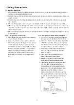
1 Safety Precautions 

1.1. General Guidelines 

1. When servicing, observe the original lead dress. If a short circuit is found, replace all parts which have been 

overheated or damaged by the short circuit. 

2. After servicing, see to it that all the protective devices such as insulation barriers, insulation papers shields are 

properly installed. 

3. After servicing, make the following leakage current checks to prevent the customer from being exposed to 

shock hazards. 

4. When conducting repairs and servicing, do not attempt to modify the equipment, its parts or its materials. 

5. When wiring units (with cables, flexible cables or lead wires) are supplied as repair parts and only one wire or 

some of the wires have been broken or disconnected, do not attempt to repair or re-wire the units. Replace the 
entire wiring unit instead. 

6. When conducting repairs and servicing, do not twist the Faston connectors but plug them straight in or unplug 

them straight out. 

1.1.1. Leakage Current Cold Check 

1. Unplug the AC cord and connect a jumper between 

the two prongs on the plug. 

2. Measure the resistance value, with an ohmmeter, 

between the jumpered AC plug and each exposed 
metallic cabinet part on the equipment such as 
screwheads, connectors, control shafts, etc. When 
the exposed metallic part has a return path to the 
chassis, the reading should be 100 Mohm and 
over. When the exposed metal does not have a 
return path to the chassis, the reading must be


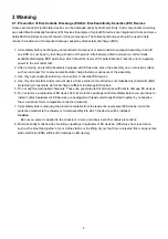
1.1.2. Leakage Current Hot Check (See Figure 1.) 

1. Plug the AC cord directly into the AC outlet. Do 

not use an isolation transformer for this check. 

2. Connect a 1.5kohm, 10 watts resistor, in parallel 

with 0.15

μ

F capacitors, between each exposed 

metallic part on the set and a good earth ground 
such as a water pipe, as shown in Figure 1. 

3. Use an AC voltmeter, with 1000 ohms/volt or 

more sensitivity, to measure the potential 
across the resistor. 

4. Check each exposed metallic part, and 

measure the voltage at each point. 

5. Reverse the AC plug in the AC outlet and 

repeat each of the above measurements. 

6. The potential at any point should not exceed 

0.75 volts RMS. A leakage current tester 
(Simpson Model 229 or equivalent) may be 
used to make the hot checks, leakage current 
must not exceed 1/2 milliamp. In case a 
measurement is outside of the limits specified, 
there is a possibility of a shock hazard, and the 
equipment should be repaired and rechecked 
before it is returned to the customer. 


Figure 1 

Summary of Contents for TH-L24X5D

Page 1: ...mpt to service or repair the product or products dealt with in this service information by anyone else could result in serious injury or death IMPORTANT SAFETY NOTICE There are special components used...

Page 2: ...1 Service Hint 6 3 2 Applicable signals 7 4 Specifications 8 5 Troubleshooting Guide 10 5 1 No Power 10 5 2 Abnormal Display 11 5 3 No Display 12 5 4 Sound Problem 13 5 5 Remote Control Malfunction 1...

Page 3: ...en the jumpered AC plug and each exposed metallic cabinet part on the equipment such as screwheads connectors control shafts etc When the exposed metallic part has a return path to the chassis the rea...

Page 4: ...of the assembly 3 Use only a grounded tip soldering iron to solder or unsolder ES devices 4 Use only an anti static solder removal device Some solder removal devices not classified as anti static ESD...

Page 5: ...e solder has a higher melting point than standard solder Typically the melting point is 50 70 F 30 40 C higher Please use a high temperature soldering iron and set it to 700 20 F 370 10 C Pb free sold...

Page 6: ...out AV Terminal HDMI in SD Card PC in Digital Signal Processor Nile Tcon Tuner All boards are non serviceable and should be exchanged for service IR Board Remote Receiver LED Power Board Power AC DC...

Page 7: ...tible to VESA standard timing Applicable input signal for PC is basically compatible to HDMI standard timing Note Signals other than above may not be displayed properly The above signals are reformatt...

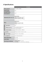
Page 8: ...8 4 Specifications...

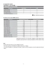
Page 9: ...9 Note...

Page 10: ...input and the power is ON Power On Power board output 5V Replace the Power board Yes No Yes No Use RC or Key to turn on the TV No Yes 1 RC can turn on the TV and Key can t replace the key board 2 Key...

Page 11: ...1 5 2 Abnormal Display Abnormal Display Replace LVDS Cable Replace the main board Replace the panel No No Yes No Enter factory mode to Reset Replace the main board No Yes Reset Check the OSD is normal...

Page 12: ...e Panel No display LED No power LED Off Replace the main board Check the backlight is On Check the LVDS cable Reinsert or replace the LVDS cable Replace the main board Replace the Panel No Yes Yes No...

Page 13: ...nd or sound abnormal Check the TV is muted adjust the volume or enter the menu to reset Replace the main board Check the audio source connection and the TV system are correct No Yes Replace the main b...

Page 14: ...ol malfunction Replace the battery Replace the remote control Whether the IR board is abnormal Yes Replace the IR board Replace the main board Yes Yes Use the other remote controls Check the remote co...

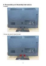
Page 15: ...15 6 Disassembly and Assembly Instructions TH L24X5D 1 Remove the screws to remove the stand...

Page 16: ...inted with front cabinet by several hooks at top and both side After remove the screws take rear cover at bottom side and pull up it forcibly just like tearing rear cover from front cabinet 3 Unplug t...

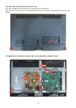
Page 17: ...17 4 Remove the Speakers 5 Remove the screws to remove the Main Board and Power Board...

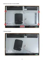
Page 18: ...18 6 Remove the screws to remove the BKT 7 Remove the panel...

Page 19: ...19 8 Remove the Key board and IR board...

Page 20: ...20 7 Block Diagram Main Board Power Board...

Page 21: ...se confirm that all flexible cables are assembled correctly Also make sure that they are locked in the connectors Verify by giving the flexible cables a very slight pull 8 2 Wiring TH L24X5D CN701 CN1...

Page 22: ...22 9 Exploded View and Replacement Parts List 9 1 Exploded View...

Page 23: ...r Cover 1 10 TZZ00000517A Key Cover 1 11 TZZ00000519A Key Pad 1 12 TZZ00000365A Key Board 1 13 TZZ00000527A Base 1 TZZ00000189A Power Cord 1 TZZ00000001A Remote Controller 1 TZZ00000457A Manual 1 TZZ0...

Reviews: