Panasonic TH-86SQ1HW Operating Instructions Manual Download Page 80

80

English


[Scenario file check]

Checks the memory selected for [Use memory select]. 

When an error is detected, the error code and file name 

are displayed.
For details of the error codes, refer to “USB memory 

contents check”. (see page 113)

Select [Scenario file check] with     and press 

<ENTER>.

Available

Scenario file check

Note

● 

When the schedule playback is proceeding using 

“Content Management Software”, [Scenario file 

check] is disabled.


[Codec information]

Displays the codec information of a motion picture/still 

picture file being played on the USB media player.
The file is analysed on execution, and the codec 

information is displayed after the completion of the 

analysis.

Note

● 

The file analysis takes time in proportion to the 

number of files in the USB memory device.

● 

A black screen appears during analysis because 

playback is stopped.

● 

Incompatible with the schedule play mode.


[Internal memory]

Performs operation of data within the internal memory.

Note

● 

When using the internal memory, refer to [Use 

memory select]. (see page 89)

● 

The capacity of the internal memory is approx. 3 GB.
[Internal memory] - submenu screen

Copy from USB memory

Internal memory

All data delete

[Copy from USB memory]:

Copies data from the USB memory device to the 

internal memory.

[All data delete]:

Deletes data in the internal memory.


[Slide show duration]

Select the displaying duration for still images.

[10 sec] to [600 sec]
Note

● 

When the schedule playback is proceeding using 

“Content Management Software”, [Slide show 

duration] is disabled.


Play mode

Specifies the playback mode operating with [Schedule 

play function]. To apply this setting to the schedule 

playback operation, restart this unit.
Also, if the playback mode is specified for the schedule 

data of “Content Management Software” during the 

schedule playback, it takes priority.

[Individual play]:

Plays in the individual playback mode.
Content is played only on one display.

[Synchronize play]:

Plays in the synchronized playback mode.
Content is played on multiple displays in 

synchronization.
Note approx. 5 seconds of preparation time are 

added in switching content to synchronize the 

playback timing.

Note

● 

The synchronized playback operates properly only 

when [Date and time] - [Synchronize display] is set to 

[On] and the time is synchronized.

● 

[Current setting] shows [Play mode] when the 

schedule playback is performed by this unit.

Memory viewer settings

Set for “Memory viewer”.
For details of the function, refer to “Memory viewer” (see 

page 119).

Note

● 

Depending on the setting for [Use memory select], 

accessing devices differ. When [USB] is selected, a 

USB memory device inserted to the 6074 terminal is 

used. When [Internal memory] is selected, the internal 

memory is used.
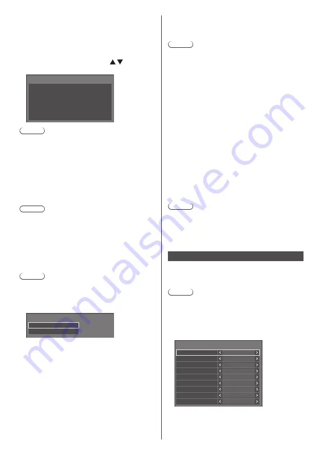
[Memory viewer settings] - submenu screen

Memory viewer settings

Memory viewer

Video

On

Enable

On

Content select

Picture duration
Auto display content info

Sort order

Sort type

Auto display operation guide

Thumbnail

View

Play method

Ascending

File name

None

10 sec


[Memory viewer]

Enables/Disables “Memory viewer”.

Summary of Contents for TH-86SQ1HW

Page 1: ...LCD Display For business use Model No TH 86SQ1HW 86 inch model TH 75SQ1HW 75 inch model English Please read these instructions before operating your set and retain them for future reference DPQP1368ZB...

Page 2: ...5 Important Safety Notice 6 Safety Precautions 8 Precautions for use 11 Accessories 14 Accessories Supply 14 Remote Control Batteries 15 Attaching the USB Memory Cover 15 Attaching the Function Board...

Page 3: ...nnecting with LAN 96 Computer operation 96 Using Web Browser Control 97 Before Using Web Browser Control 97 Access from Web Browser 97 Operating with Web Browser 98 Using USB media player 108 Function...

Page 4: ...not block any ventilation openings Install in accordance with the manufacturer s instructions 8 Do not install near any heat sources such as radiators heat registers stoves or other apparatus includi...

Page 5: ...desired operation CANADIAN NOTICE This Class A digital apparatus complies with Canadian ICES 003 WARNING Not for use in a computer room as defined in the Standard for the Protection of Electronic Comp...

Page 6: ...se interference such as noise to appear Using this appliance near sources of strong electromagnetic fields or where electrical noise may overlap with the input signals could cause the sensor function...

Page 7: ...se is replaced If you lose the fuse cover the plug must not be used until a replacement cover is obtained A replacement fuse cover can be purchased from your local Panasonic dealer Do not cut off the...

Page 8: ...lay may fall off or tip over Install this unit at a location with minimal vibration and which can support the weight of the unit Dropping or falling of the unit may cause injury or malfunction Caution...

Page 9: ...uit generates heat etc which could cause electric shock or fire Do not use the supplied power supply cord with any other devices Doing so may cause short circuit generates heat etc which could cause e...

Page 10: ...become damaged and fire or electric shock could result Disconnect the power supply plug from the wall socket as a safety precaution before carrying out any cleaning Electric shocks can result if this...

Page 11: ...l circuitry Do not grab the liquid crystal panel Do not forcibly press the liquid crystal panel or push it with a pointed object Applying a strong force to the liquid crystal panel will cause unevenne...

Page 12: ...tting up the Display at a place where electric statistic occurs often take a sufficient antistatic measure before start using When the Display is used at a location where static electricity occurs oft...

Page 13: ...h Do not use a chemical cloth for the liquid crystal panel surface Follow the instructions for the chemical cloth to use it for the cabinet Avoid contact with volatile substances such as insect sprays...

Page 14: ...VF3677ZA X1 4 pole micro plug cable 1 Approx 3 m DPVF3657ZA X1 Power supply cord Approx 2 m 1JP186SQ1HW 2JP155AF1W 3JP155AF1W Attention Store small parts in an appropriate manner and keep them away fr...

Page 15: ...not attempt to charge disassemble or burn used batteries 5 Do not burn or breakup batteries Moreover batteries must not be exposed to excessive heat such as sunshine fire or the like Attaching the US...

Page 16: ...module with a commercially sold double sided tape again Release paper Double sided tape 3 Remove the release paper from the other side of the double sided tape and attach the sensor module to the beze...

Page 17: ...ook End face End face 3 Using the screw removed in step 1 fix the function board to the SLOT adaptor Screw Tightening torque guideline 0 5 N m or less Note Firmly tighten the screw and check that the...

Page 18: ...le 75 inch model Handle Note Do not hold parts other than the handles The following number of people are required to carry this unit 86 inch model 4 or more 75 inch model 2 or more If this is not obse...

Page 19: ...mounting position two locations Eyebolt 3 After removing the eyebolt tighten the eyebolt cap Eyebolt cap Note Installation should be performed by an installation professional Do not suspend using onl...

Page 20: ...t between the AC cord connector and the AC IN terminal For the repair of the AC cord consult the dealer where you purchased the product When disconnecting the AC cord be absolutely sure to disconnect...

Page 21: ...ly Once the clamper is affixed it cannot be reused Be sure to confirm the attaching position before affixing it Attachment surface Remove the tape at the back and affix the clamper on the flat surface...

Page 22: ...this can be used to supply power of up to 5V 1A front side terminal or 5V 2A far side terminal to an external device when the picture is displayed see page 30 7 IR IN IR OUT Infrared Signal Input Out...

Page 23: ...In this case a time base corrector TBC must be connected When the sync signals output from PC or video equipment are disturbed for example when changing settings of video output the colour of the vide...

Page 24: ...Plug Detect DVI D IN terminal connection Note Video equipment and cables shown are not supplied with this unit DVI D IN terminal is for Single Link only For audio the AUDIO IN terminal can be used For...

Page 25: ...e AUDIO IN terminal For Audio input select function see page 68 Depending on the device to be connected it may take time for images to be displayed Please use DisplayPort 1 4 compliant certified cable...

Page 26: ...Plug Detect GND Ground 3 3 V DC output Daisy chain connection It is possible to daisy chain multiple displays when displaying the picture with multi screen display of the multi display etc DisplayPor...

Page 27: ...TAL LINK setting and connection refer to DIGITAL LINK Terminal connection and Precautions for use while connecting with a twisted pair cable transmitter see page 91 Corresponding signal for DIGITAL LI...

Page 28: ...e Power ON POF None Power OFF AVL Volume 000 100 AMT 0 Audio MUTE OFF 1 Audio MUTE ON IMS None Input select toggle HM1 HDMI 1 input HDMI1 HM2 HDMI 2 input HDMI2 DP1 DisplayPort IN input DisplayPort DL...

Page 29: ...ons enables the daisy chain connection Note Connection cables are not supplied with this unit Daisy chain connection is possible only between the displays of the same series Stereo mini plug M3 cable...

Page 30: ...h the periphery such as a back cover and cannot be attached Use a USB memory device connectable to this unit When connecting the USB memory device confirm the orientation of the plug to prevent damage...

Page 31: ...31 English Speaker terminal connection Use 8 15 W speaker Red Black While pressing the lever insert the core wire Return the lever...

Page 32: ...in power on status When the power indicator is purple power consumption during standby is generally larger than that of when the power indicator is orange Considering COLOR UNIVERSAL DESIGN purple lig...

Page 33: ...ge 38 10 AUTO SETUP This function does not operate 11 INPUT Switches input to display on the screen see page 36 12 PICTURE see page 46 13 SOUND see page 45 14 RECALL Displays the current setting statu...

Page 34: ...o the Display see page 20 2 Connect the plug to the socket outlet Note Main plug types vary between countries The power plug shown at left may therefore not be the type fitted to your set When disconn...

Page 35: ...NTER Note Once the items are set the screens won t be displayed when switching on the unit next time Each item can be reset in the following menus OSD language see page 71 Display orientation see page...

Page 36: ...59 Information Display upside down see page 60 Selecting the input signal Select the signals input to the unit Press INPUT or INPUT Unit Unit INPUT ENTER MENU Switches input every time the buttons are...

Page 37: ...2 Schedule play mode Off timer 90 min Backup mode OK 1 Input label 2 Aspect mode see page 39 3 Backup input change see page 63 63 4 Audio input see page 68 5 Profile name see page 50 6 Schedule play m...

Page 38: ...r the volume level is changed While MUTE is active is displayed as a reminder after operation When the image set in No signal image settings see page 70 is displayed is not displayed after operation I...

Page 39: ...icture Enlarged screen Pictures are displayed filling the screen Normal Pictures are displayed with the aspect ratio of input signals Native Pictures are displayed with the resolution of input signals...

Page 40: ...a public showing and then use the aspect mode select function to shrink or expand the picture you may be violating the copyright under copyright law It is prohibited to show or alter the copyrighted m...

Page 41: ...4 Exit the digital zoom mode Press RETURN to exit the mode The screen returns to the previous state just before entering the digital zoom mode and the digital zoom operation guide display disappears P...

Page 42: ...ur Hue Sharpness Gamma Memory save Memory load Memory edit High Enhance level 6500K Colour temperature Dynamic contrast Colour enhancement Off Off Refine enhancer Colour management Gradation smoother...

Page 43: ...saver Multi display settings Input label Power management settings Off timer function No activity power off OSD language Enable Disable English UK Image settings HDMI CEC settings Input lock Off Audio...

Page 44: ...t Note When using Screen Transfer input Position cannot be set Settings for Position are memorised separately for each input signal About Position setting Even if the display is installed vertically t...

Page 45: ...H US OSD language Sound mode and Normal are displayed as AUDIO MENU and STANDARD Bass Adjusts low pitch sounds Treble Adjusts high pitch sounds Surround Off Normal sound On Surround sound Note Bass Tr...

Page 46: ...re source or environment where this unit is used Vivid signage Suitable for signage applications featuring more vivid and sharper images in bright environments such as a shop Natural signage Suitable...

Page 47: ...temperature settings User1 and User2 can be stored 1 Press ENTER while setting Colour temperature 2 2 6500K Gamma Colour temperature Example When Colour temperature is 6500K it is possible to reflect...

Page 48: ...and press ENTER In ENGLISH US OSD language Hue is displayed as TINT Note When 6 segment is selected R red G green B blue and complementary colours cyan magenta and yellow are adjusted respectively Whe...

Page 49: ...her Memory save Memory load Memory edit Off Off Off Off High Dynamic contrast Colour management Gamma 2 2 Blue light reduction Off Memory save see page 50 Memory load see page 50 Memory edit see page...

Page 50: ...T U V W X Y Z _ Ok Cancel All delete Delete 6 When you finished entering the profile name select Ok with and press ENTER MY MEMORY1 0 1 2 3 4 5 6 7 8 9 A B C D E F G H I J K L M N O P Q R S T U V W X...

Page 51: ...th and press ENTER Memory delete Delete the MEMORY1 data Ok Cancel Renaming profiles 1 In the Picture menu select Memory edit with and press ENTER Memory save Memory load Memory edit 2 Select Memory n...

Page 52: ...SETUP to exit from adjust mode To return to the previous screen Press RETURN Multi display settings Set the screen display mode Note Set the input to something other than Screen Transfer MEMORY VIEWE...

Page 53: ...creen configuration of the main screen and sub screen two input images are displayed simultaneously 2 1 2 1 2 1 1 2 Picture by picture With two screen configuration of top and bottom screens or right...

Page 54: ...ngle of view for Position see page 44 Then set Multi screen display to On Again make fine adjustment of the angle of view for Position The Position menu can be adjusted in the multi screen display sta...

Page 55: ...f setting for Multi screen display Note When any of 1 to 4 is set and signals over a vertical frequency of 60Hz are input the unit may not perform control operation as intended Also if signals over 2...

Page 56: ...displayed Note 16 9 V fit and 16 9 H fit keep the aspect ratio 16 9 but Full doesn t Bezel adjustment Adjusts the area of image hidden in the joint area on the portrait screen 0 to 100 Location Assign...

Page 57: ...nals Note Set for each input terminal HDMI 1 HDMI 2 DisplayPort DIGITAL LINK DVI D IN SLOT With DIGITAL LINK input it is possible to set to YUV and RGB only It cannot be set to Auto Cinema reality Fai...

Page 58: ...e 4K 30p Sets EDID compatible with 4K video signals Max 4 096 x 2 160 dots Max vertical operation frequency 30 Hz 2K Sets EDID compatible with 2K video signals Max 1 920 x 1 200 dots Note If 4K 60p SD...

Page 59: ...s set to On the volume cannot be set to the level higher than the level set for Maximum VOL level Power ON screen delay When multiple displays are installed and are turned on simultaneously this funct...

Page 60: ...ng Custom Repeatedly searches Current input 1st search input and 2nd search input in order and switches to an input with a signal Input detection Monitors the inputs set to On detect the status change...

Page 61: ...t mode is set to Input detection see page 66 Input lock is not set to Off see page 71 When Setup Image settings No signal image settings Display setting is set to On see page 70 SLOT power link is set...

Page 62: ...en the same signal formats it is possible to switch within 1 second If switching between the different signal formats picture noise is caused Normal speed If switching between the same signal formats...

Page 63: ...turn to the former main input when the former input video initially viewed is restored while viewing the video of the backup input enabled by the operation of the Backup Input function Disable Unretur...

Page 64: ...er settings Screensaver operation When the Screensaver is operating the following 5 patterns are displayed full screen for 5 seconds each and it will be repeated Black Dark grey Grey Light grey White...

Page 65: ...g Automatically shifts the display image to prevent image retention on the liquid crystal panel Setting this to On moves the screen position at certain intervals and displays the images Note When Mult...

Page 66: ...rates and automatically turns the power off on This operation is performed between selected terminals Note Set the Power management function to On for terminals to operate this function Extended stand...

Page 67: ...ut Power is turned on the power indicator lights up blue Note This function may not operate depending on the video output devices Power save This function adjusts the brightness of the backlight to re...

Page 68: ...Player1 Note The obtained information of either signal or HDMICEC is displayed Up to the first 16 characters obtained are displayed Wireless presentation link This menu configures the settings for wir...

Page 69: ...eration refer to Using HDMI CEC function see page 124 Input will not be switched when Setup Input lock is set When the function board is inserted to SLOT and DVI D SLOT select is set to DVI D the inpu...

Page 70: ...Set the input to something other than USB or MEMORY VIEWER and read the image One user image can be registered for Startup image settings and No signal image settings respectively Do not turn the pow...

Page 71: ...rred language Selectable languages English UK Deutsch Fran ais Italiano Espa ol ENGLISH US Chinese Japanese Russian Set up timer Sets the program to turn the power on with the specified time and video...

Page 72: ...AY 10 00 2020 01 01 Year 2020 Month Day Hour Minute 1 1 10 0 Synchronize display Off Parent or child setting Child Synchronize display setting NTP synchronization Off Time zone GMT 00 00 NTP status Cl...

Page 73: ...arent Set the time as a source of synchronization Child Synchronizes with the time of the parent Note When Synchronize display is On and Parent or child setting is Child date and time cannot be set Wh...

Page 74: ...the LAN terminal The power indicator lights purple when the power is turned off with the remote control standby Note When using the LAN control function which is described in Using Network Function se...

Page 75: ...p www crestron com For the download of RoomView Express refer to the Crestron Electronics Inc web site Provided only in English https www crestron com en US resources get roomview Note To set the sett...

Page 76: ...tings of the RADIUS server For the settings of the RADIUS server consult with the network administrator When EAP is set to EAP TLS set Date and time see page 72 and register the certificate on the WEB...

Page 77: ...IGITAL LINK not connected HDMI on DIGITAL LINK connected HDCP on HDCP supported on DIGITAL LINK Signal quality It is the quantified minimum and maximum numbers of errors that have occurred The display...

Page 78: ...rk settings Sets whether to permit the network setting using the USB memory device see page 131 Permit Permits USB memory network settings Prohibit Prohibits USB memory network settings Note This func...

Page 79: ...deo playback mode If image disturbance occurs at the switching timing of motion picture files during playback in Standard mode switch to Adjust mode Standard Plays without a black image at the joint b...

Page 80: ...When the schedule playback is proceeding using Content Management Software Slide show duration is disabled Play mode Specifies the playback mode operating with Schedule play function To apply this set...

Page 81: ...is automatically erased after a certain period of time Auto display operation guide When this is set to On the operation guide is automatically displayed at the beginning of the content playback and...

Page 82: ...management settings Network settings Multi display settings Portrait settings Pressing the numeric button displays the menu screen Pressing the button again exits the menu screen AV mute Pressing the...

Page 83: ...he display position of the on screen menu changes Display example Left Centre Menu display duration Sets the display duration time for the on screen menu 5 sec to 180 sec Onscreen display Set to displ...

Page 84: ...he factory default state Options submenu screen Display information Options Software licenses Cloning password USB data cloning Security password LAN data cloning Output log data Shipping Display info...

Page 85: ...on switching to On Note To use the Controller ID function setting ID numbers both for the remote control and for the display unit is required For ID number setting for the remote control see page 133...

Page 86: ...e sensor 10 cm or less Skips to the previous playback file Hold a hand etc away from the sensor approx 20 cm Skips to the next playback file The distances are approximate and change depending on the c...

Page 87: ...is connected if there is no playable file the unit determines no signal is present Temperature warning When set to On the display sends out the warning message SLOT settings Set for SLOT This menu is...

Page 88: ...TER Unit for 4 times Press Unit for 4 times Press ENTER Unit MENU ENTER Press ENTER Unit for 4 times Press Unit for 4 times Press INPUT Unit for 4 times Press ENTER Unit Note About how to reset the se...

Page 89: ...d for power supply see page 30 Quick input change mode Sets the mode to switch the input at high speed Off Switches the input in normal mode On Switches the input in high speed mode between the follow...

Page 90: ...r 11 0 Windows Safari 8 0 9 0 10 0 11 0 Mac OS Microsoft Edge Example of network connection Note To use the network function set each item in Network settings and make sure to set Network control to O...

Page 91: ...transmission distance between the twisted pair cable transmitter and the device is up to 100 meters When transmitting 4K signal the maximum is 50 meters Exceeding this distance can cause cropped imag...

Page 92: ...Setup Network settings LAN control protocol is set to Protocol 1 or Protocol 2 1 When LAN control protocol is set to Protocol 1 Communicates using the display specific protocol Connection method 1 Obt...

Page 93: ...LAN control protocol is set to Protocol 2 Communicates with the same protocol as that of a Panasonic projector Connection method 1 Obtain the display s IP address and the port number Default is 1024 a...

Page 94: ...on command usage For more details visit the following web site https panasonic net cns prodisplays PJLink protocol The unit s Network function is compatible with PJLink Class 1 and Class 2 The follow...

Page 95: ...rsion number Class Command Control 2 INNM Input terminal name query Returns the input terminal name 31 HDMI1 32 HDMI2 33 DisplayPort 34 DIGITAL LINK 35 DVI D 36 SLOT 41 USB Internal Memory 42 MEMORY V...

Page 96: ...net cns prodisplays Note This unit does not support the Auto Display Adjustment Upgrade Kit TY VUK10 Content Management Software This unit supports Content Management Software to create schedule data...

Page 97: ...proxy server for your LAN boxes 4 Click OK Enable JavaScript 1 Display Internet Properties window Click Start Settings Network Internet Ethernet Network and Sharing Center Internet Options 2 Set the s...

Page 98: ...several minutes When using Detailed set up see page 99 or Crestron Connected see page 105 log in with the administrator rights Depending on the browser displayed operations may change Under no circums...

Page 99: ...sic operations of the unit can be performed Click Display control Basic control Power On Off control Use these to select the input signals AUDIO mute Switches aspect mode Detail control page The detai...

Page 100: ...P is set to EAP TLS USER NAME Enter the user name for authentication with one byte alphanumeric characters excluding space Up to 64 characters PASSWORD Enter the password for authentication with one b...

Page 101: ...set Time zone Synchronize display and NTP synchronization cannot be set as well When SYNCHRONIZE DISPLAY is set to ON CHILD it is not possible to set NTP SYNCHRONIZATION Date or Time When NTP SYNCHRO...

Page 102: ...and make the setting SNMP v3 USER USER NAME Enter the user name of SNMP v3 PERMISSION Select whether to obtain only information via SNMP v3 or to both obtain information and make the setting SECURITY...

Page 103: ...uration used For MIB Management Information Base of this unit see the web site below https panasonic net cns prodisplays For the settings of the SNMP manager consult with the network administrator Cha...

Page 104: ...ds of PC and other devices The following are recommendations in complexity when changing passwords For both administrator privileges and user privileges Include at least 3 kinds of characters from the...

Page 105: ...the power of the Display is turned off this operation is not available Operation buttons on the menu screen Operates on the menu screen Image quality adjustments Operate items related to image qualit...

Page 106: ...to the administrator who uses Crestron Connected Download Screen Transfer software that sends a screen of PC to the display via wired LAN can be downloaded Click Download The download screen appears...

Page 107: ...control button operation set for Setup Controller user level see page 88 does not apply Avoid operating the multiple Browser Remote Control simultaneously The same operations are applicable to both a...

Page 108: ...ngs see page 79 Using the content list delivery function of the Multi Monitoring Control Software see page 96 content still motion pictures played back on a USB media player and the playback list can...

Page 109: ...supports RGB only bmp Windows Bitmap Number of pixels Minimum 32 x 18 Maximum 4 096 x 4 096 1 bit 4 bits 8 bits 24 bits Following formats are not supported Run length encoding bit field top down trans...

Page 110: ...he file and then click Get Info 2 Click Details Scenario The play order and time can be specified for a play file Save under the name one byte alphabetical characters scenario dat immediately below ro...

Page 111: ...g 1 2 001_Contents_Video1 wmv 2 3 002_Contents_Video2 wmv 2 4 003_Contents_Video3 wmv 2 1 Played for the duration set in Slide show duration 2 Played for the duration of the play time of the file Sing...

Page 112: ...The second and subsequent lines Enter File definition File name Setting example Parent side USB memory contents filelist dat scenario dat L_Introduction jpg L_Contents_Video1 wmv L_Contents_Video2 wmv...

Page 113: ...ows Error code Detail of the error 1 No USB memory is inserted 2 scenario dat filelist dat cannot be opened 3 There is an error in the contents of scenario dat filelist dat 4 The play file format is n...

Page 114: ...performed normally Starting ending Media Player Note Select the USB terminal to be used with USB select see page 89 Depending on the USB terminal the amount of electricity supplied to an external devi...

Page 115: ...Portrait settings Digital zoom The screen and audio quality while editing the playlist is adjusted with the same content as that for the MEMORY VIEWER input Editing the playlist requires 2 MB or more...

Page 116: ...es is displayed on the right side of the file name When the content file is deleted with 4 a confirmation screen is displayed before deletion If 999 content files already exist another file cannot be...

Page 117: ...444 YUV442 and YUV440 Colour mode supports RGB only bmp Windows Bitmap Number of pixels Minimum 32 x 18 Maximum 2 000 x 2 000 1 bit 4 bits 8 bits 24 bits Following formats are not supported Run length...

Page 118: ...in synchronization To play back in the synchronized playback mode set the following for correct operation Set USB media player to Enable Set Schedule play function to Enable Set Synchronize display t...

Page 119: ...before schedule play mode is stopped is played back from the beginning When set to Off The playlist scheduled to be played back at the current time is played back from the beginning Note When playback...

Page 120: ...quency kHz Bit rate kbps MP3 8 11 025 12 16 22 05 24 32 44 1 48 8 320 WMA Standard 32 384 WMA 9 32 384 WMA 10 Pro 32 384 LPCM 64 1 536 Supported quantization bit 8 16 24 32 AAC LC 8 1 440 HE AAC Ver 2...

Page 121: ...ack or thumbnail display Displaying the Memory viewer screen Press INPUT to switch the input to MEMORY VIEWER Assigning Input function to the numeric buttons 1 to 6 can switch to MEMORY VIEWER with a...

Page 122: ...In the thumbnail view the file list view press to select the file you want to play Note When Play method is Select or Program press VOL VOL to specify the file you want to play see page 81 File selec...

Page 123: ...y will rewind and 6 will fast forward the video The speed changes in 2 steps each time you press the button and returns to the normal play Skip to the previous file Skip to the next file Play from the...

Page 124: ...his unit is turned on with the Power off on setting the device that was viewed or listened last is turned on When this unit is turned on with the Power off on setting and the device that was viewed or...

Page 125: ...r scenes are skipped forward by the number of pressed times Stop Displays the setting menu of the device MENU code see page 69 Controls the power of the device Note It is possible to operate HDMI CEC...

Page 126: ...ton each time will switch between the 1 screen display and the 4 screen display 1 2 3 4 1 1 screen display 4 screen display Switching 4 screens to 1 screen During the 4 screen display select a screen...

Page 127: ...cannot be copied Setting is required for each display Cloning password Security password Date and time Network settings Administrator account settings Network settings PJLink settings Network settings...

Page 128: ...isplayed 7 Select Display USB memory with and press ENTER Select copy type Display USB memory USB memory Display 8 Select Yes with and press ENTER Data copy to the USB memory starts Data to USB memory...

Page 129: ...removed in the step 9 the Cloning password screen is displayed Copying data to other display via LAN 1 Display Setup menu pressing SETUP 2 Select Options with and press ENTER The following display ap...

Page 130: ...2 168 0 1 192 168 0 2 192 168 0 4 192 168 0 25 192 168 0 31 192 168 0 7 192 168 0 124 192 168 0 211 LAN data cloning Status Cloning finished Display name IP address If the data copy has finished the m...

Page 131: ...size Model name _LAN_SETTINGS A Specifies the IP address S Specifies the subnet mask G Specifies the gateway address P Specifies the port number to use for the command control I Setting this to ON can...

Page 132: ...a to the display 1 Insert the USB memory device to the USB terminal on the bottom of the display USB memory USB terminal 2 The LAN setup screen is displayed after data copy has finished 3 Remove the U...

Page 133: ...85 2 Set the remote control s ID MODE switch to ON 3 Pointing the remote control at the Display you want to control press ID SET 0 ID set Display ID Controller ID 4 Press one of 0 9 Sets the tens dig...

Page 134: ...j k l m n o p q r s t u v w x y z _ Ok Cancel All delete Delete Switches the keyboard to the upper case alphabet Each time ENTER is pressed the keyboard is switched in the order of lower case upper c...

Page 135: ...24 00 74 25 D H DL DP 2K 25p 2 048 x 1 080 28 13 25 00 74 25 D H DL DP 2K 30p 2 048 x 1 080 33 75 30 00 74 25 D H DL DP 2K 48p 2 048 x 1 080 54 00 48 00 148 50 D H DL DP 2K 60p 2 048 x 1 080 67 50 60...

Page 136: ...56 D H DL DP 1280 x 800 60 1 280 x 800 49 31 59 91 71 00 D H DL DP 1280 x 800 60 1 280 x 800 49 70 59 81 83 50 D H DL DP 1280 x 960 60 1 280 x 960 60 00 60 00 108 00 D H DL DP 1280 x 1024 60 1 280 x 1...

Page 137: ...s are as follows D DVI D DVI D IN H HDMI HDMI 1 HDMI 2 DL DIGITAL LINK DIGITAL LINK DP DisplayPort DisplayPort The analogue input supports onG and onY 3 Based on VESA CVT RB Reduced Blanking standard...

Page 138: ...and press ENTER Shipping Yes No 4 Select Yes with and press ENTER The message Shipping Wait a moment will be displayed 5 After the message Please turn off the power is displayed turn the power off pr...

Page 139: ...or more than 5 seconds Shipping is displayed and the lock is released when it disappears Shipping Yes Settings for Button lock Controller user level and Controller ID function will be back to Off Init...

Page 140: ...inset it again after 5 seconds or more to turn the power on see page 34 Power automatically turns off unexpectedly Check the settings of No signal power off HDMI1 power management HDMI2 power managem...

Page 141: ...Noise is disturbing The volume balance between vocals and musical instruments is poor when listening to music Check that Auto volume is not active Min Mid Max see page 45 Sound distortion or noise an...

Page 142: ...quid crystal panel the edges may appear to flicker in the fast moving parts of the images This is normal and not indicative of malfunctioning There may be red spots blue spots green spots and black sp...

Page 143: ...22 75 inch model 1 684 mm 962 mm 96 mm excluding handles 82 mm 66 28 37 86 3 75 excluding handles 3 22 Mass 86 inch model Approx 57 8 127 4 lbs net 75 inch model Approx 42 2 93 0 lbs net Power source...

Page 144: ...nector 2 TYPE A DC 5V 1A front side terminal DC 5V 2A far side terminal EXT SP 8 30 W 15 W 15 W 10 THD SENSOR IN 4 pole mini jack 2 5 mm 1 Sound Speakers 15 mm 25 mm 1 70 mm 1 2 pieces Audio Output 20...

Page 145: ...o any third party who contacts us at the contact information provided below for a charge no more than our cost of physically performing source code distribution a complete machine readable copy of the...

Page 146: ...Batteries Only for European Union and countries with recycling systems These symbols on the products packaging and or accompanying documents mean that used electrical and electronic products and batt...

Reviews: