


SERIAL
PC IN
AUDIO
SLOT1
SLOT3
P
R
/C
R
/R
P
B
/C
B
/B
Y/G
COMPONENT/RGB IN
LAN
SLOT2
AUDIO
1
2
1
2
1
2
1
2
8
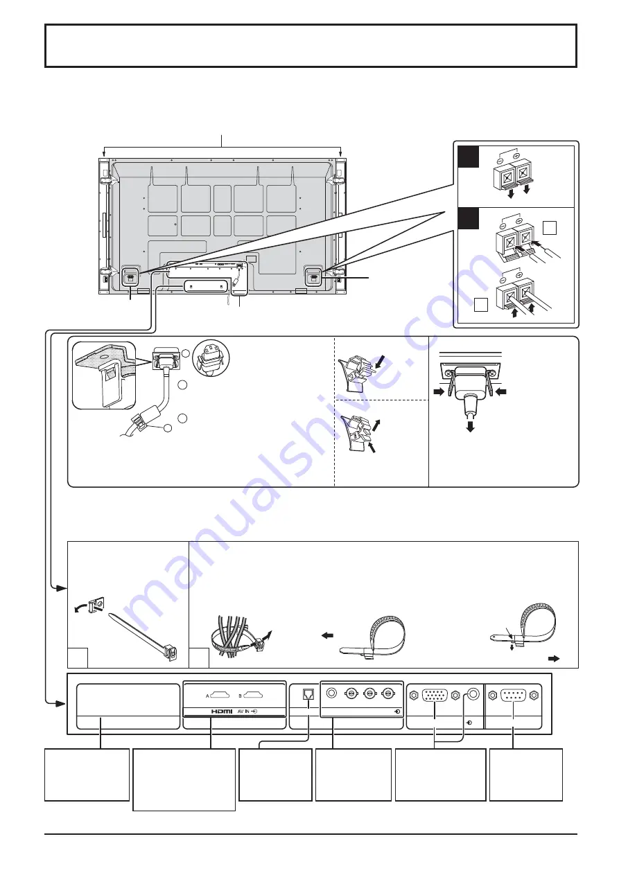
Connections
Speaker
terminal (R)
Speaker
terminal (L)
When connecting the speakers, be sure to use only the optional accessory speakers.
Refer to the speaker’s Installation Manual for details on speaker installation.
AC cord connection (see page 12)
Speakers (Optional accessories)
Pass the attached cable
xing band through the clip
as shown in the gure.
To secure cables connected to Terminals, wrap the cable xing band around them
then pass the pointed end through the locking block, as shown in the gure.
While ensuring there is suf cient slack in cables to minimize stress (especially
in the power cord), rmly bind all cables with the supplied xing band.
To tighten:
To loosen:
Pull
Pull
Push the catch
– AC cord xing
Note:
At factory shipment, Terminal boards are installed in SLOT 2 and SLOT 3.
– Cable xing band
Secure any excess cables with band as required.
Note:
One xing band is supplied with this unit. In case of securing cables at two positions, please purchase it separately.
Note:
Make sure that the AC
cord is locked on both the
left and right sides.
Push
until
the hook
clicks.
2.
Pull
off.
Close
Open
1
Plug the AC cord into the display
unit.
Plug the AC cord until it clicks.
2
Fix the AC cord with the clamper
which is attached to the unit.
For the TH-58PF12WK:
Clampers are not installed to this
unit. Ensure there is suf cient slack
in the AC cord and rmly bind with
the supplied cable xing band, etc.
1.
Keep the
knob
pressed.
Unplug the AC cord
Unplug the AC
cord pressing
the two knobs.
Note:
When disconnecting the AC cord,
be absolutely sure to disconnect
the AC cord plug at the socket
outlet rst.
From SERIAL
Terminal on
Computer
(see page 10)
From EXTERNAL
monitor terminal
on Computer
(see page 9)
Dual HDMI Terminals
(equivalent of Dual
HDMI Terminal Board
(TY-FB10HMD))
(see page 11)
Optional Terminal
Board Insert Slot
(covered)
COMPONENT/
RGB IN
Terminals
(see page 11)
LAN Terminal
(see page 57)


