background image

English

20

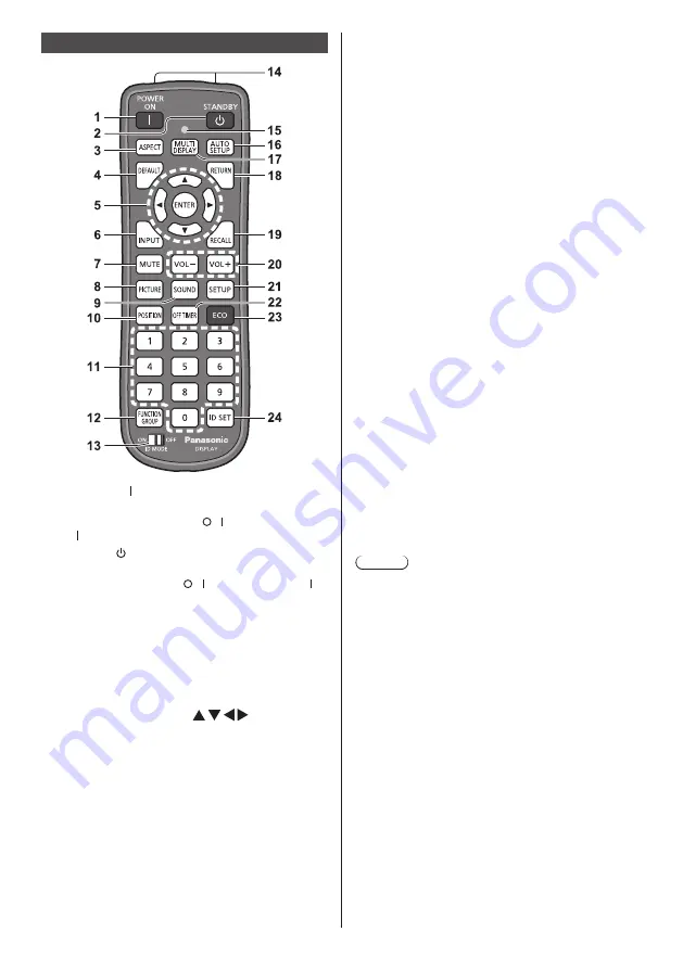
Remote Control Transmitter

1  POWER ON ( )

● 

Turns the power on (Picture is displayed.) when 

the <Main power switch> (  / ) is switched to on  

( ) and in Standby condition. (see page 21)

2  STANDBY ( )

● 

Turns the power off (Standby condition) when the 

<Main power switch> (  / ) is switched to on ( ) 

and the picture is displayed.
(see page 21)

3  ASPECT

● 

Adjusts the aspect.

4  DEFAULT

● 

Resets the settings of picture, sound, etc., to 

defaults.

5  ENTER / Cursor buttons (       )

● 

Used to operate the menu screens.

6  INPUT

● 

Switches input to display on the screen.

7  MUTE

● 

Sound mute on / off.

8  PICTURE
9  SOUND
10 POSITION

11 Numeric buttons (0 - 9)

● 

Used to input ID number when using several 

Displays.

● 

Used as shortcut buttons by assigning frequently 

used operations.

12 FUNCTION GROUP
13 ID MODE
14 Signal  emission
15 Remote control operation Indicator

● 

Flashes when remote control buttons are pressed.

16 AUTO SETUP

● 

Automatically adjusts the position/size of the 

screen.

17 MULTI DISPLAY

● 

Switches [On] / [Off] in [Multi display setting].

18 RETURN

● 

Used to return to the previous menu.

19 RECALL

● 

Displays the current setting status of Input mode, 

Aspect mode, etc.

20 VOL + / VOL -

● 

Adjusts sound volume level.

21 SETUP
22 OFF TIMER

● 

Switches to stand-by after a fixed period.

23 ECO

● 

Switches the settings of [Power management 

mode].

24 ID SET

● 

Used to set remote control ID number when using 

several Displays.

Note

● 

In this manual, buttons of the remote control and the 

unit are indicated as < >.
(Example: <INPUT>.)
The operation is mainly explained indicating the 

remote control buttons but you can also operate with 

the buttons on the unit when there are the same 

buttons.

Summary of Contents for TH-55VF2W

Page 1: ...e different from the actual ones Contents Important Safety Instructions 2 FCC STATEMENT 3 Important Safety Notice 4 Safety Precautions 6 Precautions for use 9 Accessories 11 VESA Mounting 12 Cautions when installing multi displays 13 Cautions when moving 14 LCD panel protection 14 Kensington security 15 Connections 16 Identifying Controls 19 Basic Controls 21 Specifications 23 Software License 25 ...

Page 2: ...nly with dry cloth 7 Do not block any ventilation openings Install in accordance with the manufacturer s instructions 8 Do not install near any heat sources such as radiators heat registers stoves or other apparatus including amplifiers that produce heat 9 Do not defeat the safety purpose of the polarized or grounding type plug A polarized plug has two blades with one wider than the other A ground...

Page 3: ...at may cause undesired operation CANADIAN NOTICE This Class A digital apparatus complies with Canadian ICES 003 WARNING Not for use in a computer room as defined in the Standard for the Protection of Electronic Computer Data Processing Equipment ANSI NFPA 75 For permanently connected equipment a readily accessible disconnect device shall be incorporated in the building installation wiring For plug...

Page 4: ... noise may overlap with the input signals could cause the picture and sound to wobble or cause interference such as noise to appear To avoid the possibility of harm to this appliance keep it away from sources of strong electromagnetic fields WARNING This equipment is compliant with Class A of CISPR32 In a residential environment this equipment may cause radio interference IMPORTANT INFORMATION Sta...

Page 5: ...use is replaced If you lose the fuse cover the plug must not be used until a replacement cover is obtained A replacement fuse cover can be purchased from your local Panasonic dealer Do not cut off the mains plug Do not use any other type of mains lead except the one supplied with this display The supplied mains lead and moulded plug are designed to be used with this display to avoid interference a...

Page 6: ...cts on top of the Display If foreign objects or water get inside the Display a short circuit may occur which could result in fire or electric shock If any foreign objects get inside the Display please consult your local Panasonic dealer Ventilation should not be impeded by covering the ventilation openings with items such as newspapers table cloths and curtains For sufficient ventilation see page ...

Page 7: ...enerated which could cause fire If the plug is damaged or the wall socket is loose they shall not be used Do not do anything that may damage the power cable When disconnecting the power cable pull on the plug body not the cable Do not damage the cable make any modifications to it place heavy objects on top of it heat it place it near any hot objects twist it bend it excessively or pull it To do so...

Page 8: ...ll on the plug socket outlet side the connector main unit side Pulling the cord may damage the cord and it may cause electric shock or fire due to short circuit Be sure to disconnect all cables before moving the Display If the Display is moved while some of the cables are still connected the cables may become damaged and fire or electric shock could result Disconnect the power supply plug from the...

Page 9: ...0 cm 3 94 or more at the top bottom left and right At the rear leave a space of 5 cm 1 97 or more Operation of this unit is guaranteed up to an ambient temperature of 40 C 104 F When installing the unit in a case or chassis be sure to provide adequate ventilation with a cooling fan or ventilation hole so that the surrounding temperature inside the case or chassis including the temperature of the f...

Page 10: ...lge your password in case you receive such inquiries The connecting network must be secured by a firewall etc When disposing the product initialize the data before disposing Shipping Cleaning and maintenance The front of the liquid crystal panel has been specially treated Wipe the surface of the liquid crystal panel gently using only a cleaning cloth or a soft lint free cloth If the surface is par...

Page 11: ...pprox 1 8 m DPVF1180ZA Batteries for the Remote Control Transmitter AAA R03 UM4 type 2 Clamper 3 TZZ00000694A Power supply cord Approx 2 m 1JP155AF1U 1JP155AF1W 2JP155AF1W 3JP155AF1W Attention Store small parts in an appropriate manner and keep them away from young children In case you lost accessories please consult your dealer Dispose the packaging materials appropriately after taking out the it...

Page 12: ...with Alkaline 4 Do not attempt to charge short circuit disassemble heat or burn used batteries 5 Battery replacement is necessary when remote control acts sporadically or stops operating the Display set 6 Do not burn or breakup batteries 7 Batteries must not be exposed to excessive heat such as sunshine fire or the like VESA Mounting To mount this Display using a VESA mounting bracket commercially...

Page 13: ...iple displays are installed a material to protect the top face of the LCD panel has been attached on the top face of this unit When installing multiple displays extend this protection material toward the display surface side After installing multiple displays cut off this protection material from the cutting off line and then adjust the gaps During installation After installation Cut off Protectio...

Page 14: ...ot hold the upper lower right and left frames or the corners of the unit Do not hold the front surface of the liquid crystal panel Also do not hit such parts Doing so may damage the liquid crystal panel Also the panel may crack resulting in injury When carrying the display do not apply a twisting force to the panel surface LCD panel protection Protection materials for the LCD panel have been attac...

Page 15: ...15 English Kensington security The security slot of this unit is compatible with the Kensington security cables ...

Page 16: ...ult the dealer where you purchased the product When disconnecting the AC cord be absolutely sure to disconnect the AC cord plug at the socket outlet first The supplied AC cord set is for this unit exclusive use Do not use this for other purposes Cable fixing Note 3 clampers are supplied with this unit Fix the cables at 3 locations using the holes for clampers as shown below If you need more clampe...

Page 17: ...dio signals via the DIGITAL LINK terminal Alternatively control the display by connecting to Network Also when displaying the picture by daisy chaining multiple displays connect to the other display 6 PC IN PC Input Terminal Connect to video terminal of PC video equipment with YPBPR YCBCR or RGB output 7 AUDIO1 IN Audio input terminal 1 8 IR IN IR OUT Infrared Signal Input Output Terminal Use this...

Page 18: ...ting terminal of the connecting device in a straight manner Acquire any connection cable necessary to connect the external device to the system that is neither supplied with the device nor available as an option If the outer shape of the plug of a connection cable is large it may come in contact with the plug of an adjacent connection cable Use a connection cable with the suitable plug size for th...

Page 19: ...t to On Orange Power OFF with Power management function Orange When the power of the unit is OFF Main power switch OFF No light Note When the power indicator is orange power consumption during standby is generally larger than that of when the power indicator is red MENU ENTER INPUT 1 External Input Terminal Connects to video equipment PC etc see page 17 2 Power button Unit Turns the power ON Pictu...

Page 20: ...ently used operations 12FUNCTION GROUP 13ID MODE 14Signal emission 15Remote control operation Indicator Flashes when remote control buttons are pressed 16AUTO SETUP Automatically adjusts the position size of the screen 17MULTI DISPLAY Switches On Off in Multi display setting 18RETURN Used to return to the previous menu 19RECALL Displays the current setting status of Input mode Aspect mode etc 20VO...

Page 21: ...switch immediately after changing settings with on screen menu Leave enough period of time before disconnecting the power plug or switching the display off at the Main power switch Or turn the power off with the remote control RS 232C control or LAN control before disconnecting the power plug or switching the display off at the Main power switch 3 Switch the Main power switch ON To turn the power ...

Page 22: ...eens won t be displayed when switching on the unit next time Each item can be reset in the following menus OSD language Display orientation Long life settings Power ON message The following message may be displayed when turning the unit power ON No activity power off Precautions No activity power off is enabled When No activity power off in the Setup menu is set to Enable a warning message is disp...

Page 23: ...sation Storing condition Temperature 20 C to 60 C 4 F to 140 F Humidity 10 to 90 no condensation Connection terminals HDMI TYPE A Connector 2 1 Audio signal Linear PCM sampling frequencies 48 kHz 44 1 kHz 32 kHz DisplayPort DisplayPort Terminal 1 Ver 1 1 Dual Mode only DVI D IN 1 DVI D 24 Pin 1 Compliance with DVI Revision 1 0 Content Protection Compatible with HDCP 1 1 DVI D IN 2 DVI D 24 Pin 1 C...

Page 24: ... 5V DC 500mA USB 3 0 is not supported EXT SP 8 Ω 20 W 10 W 10 W 10 THD Sound Audio Output 20 W 10 W 10 W 10 THD Remote Control Transmitter Power source DC 3 V battery AAA R03 UM4 type 2 Mass approx 102 including batteries Dimensions W H D 48 mm 145 mm 27 mm 1 89 5 71 1 06 1 Environmental temperature to use this unit at high altitudes 1 400 m 4 593 ft and higher and below 2 800 m 9 186 ft above sea...

Page 25: ...ive to any third party who contacts us at the contact information provided below for a charge no more than our cost of physically performing source code distribution a complete machine readable copy of the corresponding source code covered under GPL V2 0 LGPL V2 1 or the other licenses with the obligation to do so as well as the respective copyright notice thereof Contact Information oss cd reques...

Page 26: ...damage to the display and its components which occur in shipping failures which are caused by products not supplied by Panasonic failures which result from accident misuse abuse neglect mishandling misapplication alteration modification faulty installation setup adjustments improper antenna inadequate signal pickup maladjustment of user controls improper operation power line surge improper voltage...

Page 27: ...rtion of the original warranty coverage period Proof of product purchase is a condition of warranty service The owner must produce the product purchase receipt or other satisfactory evidence of date of original purchase This warranty does not apply to external appearance items such as handles knobs safety windows etc This warranty does not apply to any part or parts of the product installed altere...

Page 28: ...28 English Customer Service ...

Page 29: ...ina Disposal of Old Equipment and Batteries Only for European Union and countries with recycling systems These symbols on the products packaging and or accompanying documents mean that used electrical and electronic products and batteries must not be mixed with general household waste For proper treatment recovery and recycling of old products and used batteries please take them to applicable coll...

Reviews: