background image

English

13

  Connections

● 

 External equipment and cables shown are not 
supplied with this TV.

● 

 Please ensure that the unit is disconnected from the 
mains socket before attaching or disconnecting any 
cables.

● 

 Check the terminal type and cable plugs are correct 
for connection.

● 

 Use a fully wired HDMI compliant cable.

● 

 Keep the TV away from electronic equipment (video 
equipment, etc.) or equipment with an infrared sensor, 
otherwise distortion of image / sound may occur or 
operation of other equipment may be affected.

● 

 Please also read the manual of the equipment being 
connected.

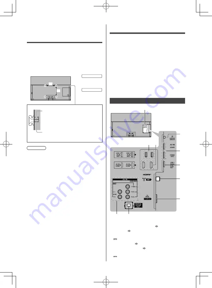
 Terminals


3

4

5

6

7

8

9

10

2

1

 1  Model name plate
 2  Headphone / Subwoofer jack   (p. 16)
 3  HDMI1 - 2   (p. 14, 15, 16)
 4   USB 1 port 

 This symbol indicates DC operation.

 5  Aerial terminal   (p. 14)
 6  ETHERNET terminal   (p. 14)
 7  USB 2 - 3 port 

 This symbol indicates DC operation.

  Installing the wall-
hanging bracket

 Choosing to wall mount the TV shall be done at the 
owner’s risk. Always use a qualified installer to perform 
a TV wall bracket installation. Incorrect fitting may cause 
equipment to fall, resulting in injury and product damage. 
Any such damage will void your warranty.

● 

 Holes for wall-hanging bracket installation
 Rear of the TV


 a

 b


55-inch model

 a: 400 mm
 b: 300 mm
 

65-inch model

 a: 400 mm
 b: 400 mm

 (View from the side)


 Depth of screw

 minimum: 23 mm
 maximum: 28 mm

 Type of screw: M6

 Screw for fixing the TV onto the 
wall-hanging bracket (not supplied with 
the TV)

 Warning

● 

 When optional accessories such as wall brackets, etc. 
are used, always read and follow the manufactures 
installation and usage instructions.

● 

 Do not mount the unit directly below ceiling lights 
(such as spotlights or halogen lights) which typically 
give off high heat. Doing so may warp or damage 
plastic cabinet parts.

● 

 When installing wall brackets you must ensure the 
wall bracket is not electrically grounded to metal wall 
studs. Always ensure that there are no electrical 
cables, pipes, etc. in the wall before you begin the 
wall bracket installation.

Summary of Contents for TH-55GZ1500U

Page 1: ...em for future reference Please carefully read the Safety Precautions of this manual before use The images shown in this manual are for illustrative purposes only Model No TH 55GZ1500U TH 65GZ1500U For more detailed instructions please refer to eHELP Built in Operating Instructions How to use eHELP p 20 image TH 65GZ1500U Operating Instructions OLED TV English ...

Page 2: ...t Notice 3 Safety Precautions 5 Accessories 7 Installing the TV 8 Installing the wall hanging bracket 13 Connections 13 Identifying Controls 17 First time Auto Tuning 19 Watching TV 20 How to Use eHELP 20 FAQs 22 Maintenance 23 Specifications 24 ...

Page 3: ... Purpose Watching For best picture For more information Panel maintenance p 18 Internet apps are provided by their respective service providers and may be changed interrupted or discontinued at any time Panasonic assumes no responsibility and makes no warranty for the availability or the continuity of the services Panasonic does not guarantee operation and performance of peripheral devices made by...

Page 4: ...e and Settings When using Internet connecting function of this TV after agreeing in the jurisdictions where customer s consent is required to collect personal information under applicable privacy laws to or reviewing Panasonic s terms of service privacy policy hereinafter referred to as terms and conditions etc customer information on the use of this unit may be collected and used according to ter...

Page 5: ... support Not placing the TV on cloth or other materials that may be located between the TV and supporting furniture Educating children about the dangers of climbing on furniture to reach the TV or its controls If your existing TV is being retained and relocated the same considerations as above should be applied This TV is designed for indoor use This TV is designed for table top use Do not expose ...

Page 6: ... curtains Whether you are using a pedestal or not always ensure the vents at the bottom of the TV are not blocked and there is sufficient space to enable adequate ventilation Moving the TV Caution Before moving the TV disconnect all cables At least two people are required to move the TV to prevent injury that may be caused by the tipping or falling of TV To prevent the spread of fire keep candles ...

Page 7: ...to a live mains socket Remove the mains plug from the wall socket when the TV is not in use for a prolonged period of time Excessive volume Caution Do not expose your ears to excessive volume from the headphones Irreversible damage can be caused If you hear a drumming noise in your ears turn down the volume or temporarily stop using the headphones Battery for the Remote Control Caution Incorrect i...

Page 8: ...not hold the screen panel part Make sure not to scratch or break the TV Do not place the TV temporarily on the floor or desk Assembling the pedestal Insert the pedestal firmly otherwise it may come off when setting up the TV Do not assemble the pedestal by any method other than those specified below ...

Page 9: ...ble clamp Attach the cable clamp Insert the cable clamp in a hole Hole Bundle the cable Set To release Keep pushing the tab Tab Tab To remove from the TV Keep pushing both side snaps Snaps Connecting the cables Removing the terminal cover Be sure to remove the terminal cover before connecting or disconnecting cables When the connections are completed attach the terminal cover pedestal cover p 11 T...

Page 10: ...y follow the option s assembly manual to fix cables Fixing the cables using the cable tie Attach the cable tie Insert the cable tie in a hole Hole Bundle the cables Hooks Set the tip in the hooks To loosen Knob Keep pushing the knob To remove from the TV Keep pushing both side snaps Snaps ...

Page 11: ... the TV and the terminal cover pedestal cover When using USB 2 port USB 3 port AV IN terminal DIGITAL AUDIO OUT HDMI3 terminal or HDMI4 terminal you cannot attach the terminal cover Keep the removed terminal cover for future use Do not apply load to the terminal cover pedestal cover Terminal cover ...

Page 12: ...the TV falling over However no measure can guarantee protection in all cases Attaching the fall prevention parts Screw 1 Wood screw 1 Band 1 F E D Removing the pedestal Be sure to remove the pedestal in the following procedures when you use the wall hanging bracket or repack the TV 1 Remove the pedestal cover 2 Remove the assembly screws from the pedestal 3 Pull out the pedestal from the TV C To r...

Page 13: ...e TV shall be done at the owner s risk Always use a qualified installer to perform a TV wall bracket installation Incorrect fitting may cause equipment to fall resulting in injury and product damage Any such damage will void your warranty Holes for wall hanging bracket installation Rear of the TV a b 55 inch model a 400 mm b 300 mm 65 inch model a 400 mm b 400 mm View from the side Depth of screw ...

Page 14: ...ed Twist Pair STP LAN cable 8 HDMI3 4 9 AV IN COMPONENT VIDEO p 15 10DIGITAL AUDIO OUT p 16 To watch content in 4K format use HDMI terminal p 15 Basic connections Mains lead AC 220 240 V 50 60 Hz Mains lead Cable tie Bundled the mains lead To loosen Knob Keep pushing the knob To remove from the TV Keep pushing both side snaps Snaps Aerial TV RF cable Aerial For Digital TV Analogue TV Keep RF aeria...

Page 15: ... the equipment Mode1 For better compatibility Set to Mode1 when the image or sound in HDMI input is not played properly Mode2 For the 4K compatible equipment that has the function to output the image precisely with the expanded colour gamut To change the mode 1 Select the HDMI input mode connected to the equipment 2 Display the menu and select HDMI Auto Setting Setup Menu For information about the...

Page 16: ...L AUDIO IN e g Amplifier with speaker system Headphones To use headphones set Headphone Terminal Output to Headphone For information about the volume settings refer to eHELP Search by Purpose Settings Sound TV 3 5 mm stereo mini plug Subwoofer To use the subwoofer set Headphone Terminal Output to Sub Woofer For information about the headphone terminal output settings refer to eHELP Search by Purpo...

Page 17: ...r details refer to eHELP Search by Purpose Home Apps 15 Light Lights the buttons for about 5 seconds Press again to turn off the button lights 16 Input mode selection TV switches to Digital TV Analogue TV AV switches to AV input mode from Input Selection list 17 Exit Returns to the normal viewing screen 18 Cursor buttons Makes selections and adjustments 19 Return Returns to the previous menu page ...

Page 18: ...maintenance as following Normal maintenance automatically starts and it takes approx 10 minutes Regular maintenance takes approx 80 minutes When regular maintenance is necessary the message appears on the screen after turning the TV off with the remote control Follow the on screen instructions During the panel maintenance a white horizontal line appears on the screen for a while This is not a malf...

Page 19: ...search for available TV channels and give options to set up the TV These steps are not necessary if the setup has been completed by your local dealer Please complete connections p 13 16 and settings if necessary of the connected equipment before starting Auto Tuning For information about the settings for the connected equipment read the manual of the equipment 1 Plug the TV into a live mains socke...

Page 20: ...First page or to the Last viewed page 2 Select the menu select access To access How to use green Keyword Search Search the content of eHELP in the keyword Search by Purpose Search the content of eHELP for each item Support Access the support information FAQs etc 3 Select the item Example select access To return to the previous screen field Watching TV 1 Turn power on TV or Remote Control Mains pow...

Page 21: ...n if more than 1 page While the description is highlighted To open the reference screen To display the menu related to the description only for some descriptions red To check the features of this TV Search by Purpose Read first Features ...

Page 22: ...n System Menu Setup Menu The image or sound from external equipment are unusual when the equipment is connected via HDMI Set HDMI Auto Setting Setup Menu to Mode1 p 15 No sound is produced from the connected HDMI equipment Set the audio output format of the connected HDMI equipment to PCM Parts of the TV become hot Parts of the TV may become hot These temperature rises do not pose any problems in ...

Page 23: ...de as it may lead to product failure 4 Carefully wipe moisten and wipe away the stubborn dirt 5 Finally wipe away all the moisture Caution Do not use a hard cloth or rub the surface too hard otherwise this may cause scratches on the surface Take care not to subject the surfaces to insect repellent solvent thinner or other volatile substances This may degrade surface quality or cause peeling of the...

Page 24: ...W 2 160 H Panel OLED panel Sound Speaker output 50 W 10 W 2 15 W 2 Headphones Subwoofer 3 5 mm stereo mini jack 1 Connection terminals AV IN COMPONENT VIDEO VIDEO Pin jack 1 1 0 V p p 75 AUDIO L R Pin jack 2 0 5 V rms Y 1 0 V p p including synchronisation PB CB PR CR 0 35 V p p HDMI1 2 3 4 input TYPE A Connectors HDMI1 3 4 4K Content Type Deep Colour x v Colour HDMI2 4K Content Type Audio Return C...

Page 25: ... 5 85 GHz IEEE802 11b g n 2 400 GHz 2 4835 GHz Security WPA2 PSK TKIP AES WPA PSK TKIP AES WEP 64 bit 128 bit Bluetooth wireless technology 2 Standard Compliance Bluetooth 4 2 Frequency Range 2 402 GHz 2 480 GHz 1 The frequency and channel differ depending on the country 2 Not all the Bluetooth compatible devices are available with this TV Up to 5 devices can be used simultaneously Note Design and...

Page 26: ...th the Authorised Service centre that you choose Then send or take the product to a Panasonic Authorised Service Centre together with your proof of purchase receipt Any freight and insurance costs associated with the transport of the product to and or from your nearest Authorised Service Centre must be arranged and paid for by you 7 The warranties hereby conferred do not extend to and exclude any ...

Page 27: ...ibuted in New Zealand by Panasonic New Zealand Limited 18 Sir Woolf Fisher Drive Highbrook East Tamaki Private Bag 14911 Panmure Auckland Tel 09 272 0100 Customer Care Center Email Customerservice nz panasonic com www panasonic co nz NEW ZEALAND ...

Page 28: ...ber label located on side or bottom of the rear panel You should note this serial number in the space provided below and retain this book plus your purchase receipt as a permanent record of your purchase to aid in identification in the event of theft or loss and for Warranty Service purposes Model Number Serial Number Web Site http www panasonic com Panasonic Corporation 2019 English Printed in Ma...

Reviews: