background image

26

MUTE

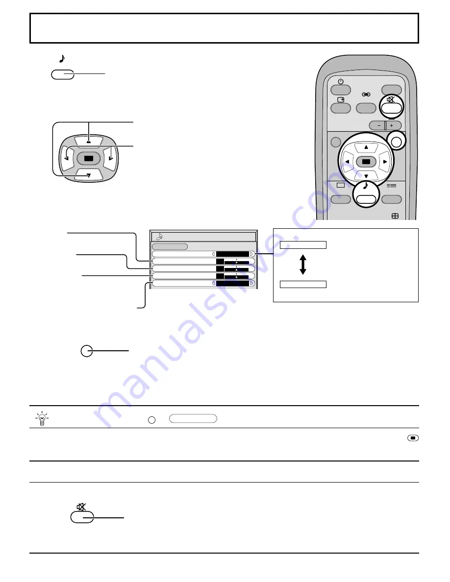
SOUND

NORMALIZE

AUDIO  MENU
BASS
TREBLE

STANDARD

ON

0

0

0

BALANCE
SURROUND

NORMAL

SOUND Adjustment

1

2

Select to adjust each item.

Press to select the desired adjustment menu.

Select the desired level by listening to the sound.

Automatically controls
proper volume level.

Emits the original sound.

BASS
Adjusts low sounds

TREBLE
Adjusts high sounds

BALANCE
Adjusts left and right
volumes

SURROUND (see next page)

Press the R button

Useful when answering the phone or receiving visitors.

Press this button to mute the sound.
Press again to reactivate sound. Sound is also reactivated when power is turned off or
volume level is changed.

SURROUND

VOL

N

PICTURE

SET UP

PICTURE

POS S

INPUT

R

SOUND

AUTO

STANDARD

R

While the “SOUND” menu is displayed, if either the N button on the remote control is pressed at any time or the 
(ACTION button) is pressed during “NORMALIZE”, then all adjustment values are returned to the factory settings.

 Helpful Hint (    / 

NORMALIZE

 Normalization)

N

• 

To end adjustments

Note:
Press the SURROUND button to directly turn the surround effect ON and OFF. (see next page)
BASS, TREBLE and SURROUND settings are memorized separately for each SOUND mode (STANDARD, AUTO).

Select ON or OFF

SOUND

Press to display the Sound menu.

Summary of Contents for TH-50PHD5

Page 1: ...tions TH 42PHD5 TH 50PHD5 Model No R STAND BY G POWER ON INPUT VOL POWE R PLASMA DISPLAY Before connecting operating or adjusting this product please read these instructions completely Please keep thi...

Page 2: ...appliance WARNING 1 To prevent electric shock do not remove cover No user serviceable parts inside Refer servicing to qualified service personnel 2 Do not remove the grounding pin on the power plug T...

Page 3: ...s have been adhered to 9 Do not defeat the safety purpose of the polarized or grounding type plug A polarized plug has two blades with one wider than the other A grounding type plug has two blades and...

Page 4: ...RROUND Controls 27 PICTURE Adjustments 28 ADVANCED SETTINGS 29 SET UP TIMER 30 PRESENT TIME OF DAY Set 30 TIMER Set 31 SCREENSAVER For preventing after images 32 Setup of SCREENSAVER Time 33 SIDE BAR...

Page 5: ...the ferrite core The ferrite cores provided as a supplied accessory must be used when connecting this Plasma Display to video equipment see page 15 16 17 FCC STATEMENT FCC CAUTION To assure continued...

Page 6: ...heat may be generated which could cause fire If the plug is damaged or the wall socket plate is loose they should not be used Do not handle the power cord plug with wet hands Doing so may cause electr...

Page 7: ...ng dusty Built up dust on the power cord plug can increase humidity which might damage the insulation and cause fire Unplug the cord from the wall outlet and clean it with a dry cloth Cleaning and mai...

Page 8: ...t angled TY WK42PR1 Remote Control Transmitter EUR646525 For assembling Full instructions are supplied with each of the optional accessories for use with this Plasma Display Mobile stand TY ST42PF3 Wa...

Page 9: ...stallation can cause battery leakage and corrosion that will damage the remote control transmitter Observe the following precautions 1 Batteries should always be replaced as a pair Always use new batt...

Page 10: ...tton VIDEO S VIDEO COMPONENT RGB and PC Mode Selection Press to select VIDEO S VIDEO COMPONENT RGB and PC input signal modes sequentially see page 19 Sound mute On Off see page 26 VOLUME Adjustment Pr...

Page 11: ...ith bands as required SPEAKER Terminals L From EXIT monitor Terminal on Computer see page 15 Pass the attached cable fixing band through the clip as shown in the figure To secure cables connected to T...

Page 12: ...nal source equipment see page 14 to 17 Example When connecting an S VIDEO VCR Speakers Optional accessories Luminance earth Luminance in Chrominance earth Chrominance in S VIDEO 4 pin socket S VIDEO V...

Page 13: ...AUDIO 2 RCA audio cables VIDEO RCA video cable Audio OUT Video OUT R L Video input to BNC socket RCA BNC adapter plug Audio input to L R sockets AUDIO 2 RCA audio cables VCR VCR AV R L AUDIO IN VIDEO...

Page 14: ...ge 34 2 Additional equipment cables and adaptor plugs shown are not supplied with this set RGB signal R G B HD VD connection Audio input to L R sockets G B R VD HD AUDIO 2 RCA audio cables 5 BNC RGB c...

Page 15: ...e time of connection 4 Some PC models cannot be connected to the set 5 There is no need to use an adapter for computers with DOS V compatible D sub 15P terminal 6 The computer shown in the illustratio...

Page 16: ...nal name horizontal vertical COMPONENT RGB PC DVI frequency kHz frequency Hz 1 525 480 60i 15 734 59 94 2 625 575 50i 15 625 50 3 525 480 60p 31 468 59 94 4 625 575 50p 31 25 50 5 750 720 60p 45 60 6...

Page 17: ...s and lastly an ETX signal in that order If there are no parameters then the parameter signal does not need to be sent Notes 1 If multiple commands are transmitted be sure to wait for the response for...

Page 18: ...UAGE selection screen is displayed From the second time on language selection can be done from the setup menu see page 19 Select the desired language using the and keys and press the ACTION button Rem...

Page 19: ...FF and Input Signal Selection Input signals will change as follows For COMPONENT INPUT see page 34 For RGB INPUT see page 34 VIDEO COMPONENT PC VIDEO RGB PC SET UP SIGNAL SCREENSAVER COMPONENT RGB IN...

Page 20: ...OLOR STANDARD 0 0 TINT COLOR TEMP NORMAL ADVANCED SETTINGS ON PICTURE 0 0 0 SHARPNESS NORMAL NORMAL ADVANCED SETTINGS NORMALIZE BLACK EXTENSION W B HIGH R W B HIGH B 0 0 0 0 W B LOW R GAMMA 2 2 0 W B...

Page 21: ...OR SYSTEM Panasonic AUTO 4 3 ON AUTO NORMAL 3 2 PULLDOWN OFF SIGNAL VIDEO SIGNAL COMPONENT 3 2 PULLDOWN OFF SIGNAL RGB SYNC H FREQ kHz V FREQ Hz H V 31 5 60 0 SIGNAL PC SYNC H FREQ kHz V FREQ Hz H V 3...

Page 22: ...ed NORMAL ZOOM FULL Panasonic AUTO JUST ASPECT Notes 1 During RGB and PC input signal modes the mode switches between NORMAL ZOOM and FULL only 2 For a 1 125i 1 080i 750p 720p signal input during COMP...

Page 23: ...is set can detect specially encoded signals that are compatible with a wide screen monitor When a full image from the S VIDEO terminal of specially encoded video is detected by the set the screen size...

Page 24: ...ized separately for different input signal formats Adjustments for component signals are memorized for 525i 480i 625i 575i 525p 480p 1 125i 1 080i and 625p 575p 750p 720p each and RGB PC signals are m...

Page 25: ...distortion can be eliminated by using the Position Left or Right button to carry out adjustment While the PICTURE POS SIZE display is active if either the N button on the remote control is pressed at...

Page 26: ...e the sound Press again to reactivate sound Sound is also reactivated when power is turned off or volume level is changed SURROUND VOL N PICTURE SET UP PICTURE POS S INPUT R SOUND AUTO STANDARD R Whil...

Page 27: ...f you were at a concert hall or cinema The surround setting switches ON and OFF each time the SURROUND button is pressed ON OFF Note The surround settings are memorized separately for each SOUND mode...

Page 28: ...tandard evening lighting environments This menu selects the normal levels of BRIGHTNESS and PICTURE DYNAMIC For viewing in brighter environments This menu selects higher than normal levels of BRIGHTNE...

Page 29: ...More Less More N Item BLACK EXTENSION W B HIGH R W B HIGH B W B LOW R W B LOW B GAMMA Effect Less More Less More Less More Less More Details Adjusts the dark shades of the image in gradiation Adjusts...

Page 30: ...DAY HOURS ADJUSTMENT 99 99 00 MINUTES ADJUSTMENT 00 Press to display the SETUP menu screen Press to select SET UP TIMER Press to display the SET UP TIMER screen 1 2 1 2 Press to select PRESENT TIME O...

Page 31: ...MER POWER ON SETUP POWER ON FUNCTION HOURS ADJUSTMENT 0 52 00 MINUTES ADJUSTMENT 52 SET UP TIMER PRESENT TIME OF DAY POWER ON FUNCTION 0 52 OFF POWER ON TIME POWER OFF FUNCTION POWER OFF TIME 0 00 0 0...

Page 32: ...SCREENSAVER FUNCTION MODE WHITE BAR SCROLL INTERVAL SHOW DURATION SIDE BAR ADJUST BRIGHT SAVER DURATION SCREENSAVER FUNCTION MODE WHITE BAR SCROLL TIME OF DAY START TIME 0 00 0 00 SIDE BAR ADJUST MID...

Page 33: ...ADJUST HIGH SAVER DURATION SIDE BAR ADJUST 2 Press to select the SIDE BAR ADJUST Press to select OFF DARK MID BRIGHT OFF DARK MID BRIGHT R 0 00 0 00 SCREENSAVER FUNCTION MODE WHITE BAR SCROLL INTERVA...

Page 34: ...desired mode R Press to exit from adjust mode Select SIGNAL from the SET UP menu during VIDEO S VIDEO input signal mode SIGNAL VIDEO menu is displayed 3D Y C FILTER NTSC COLOR SYSTEM Panasonic AUTO 4...

Page 35: ...ically Set to NORMAL to view 4 3 images in an unchanged format when Panasonic AUTO is selected If you would like to view 4 3 images in Just format set to JUST AUTO PAL SECAM M NTSC NTSC 3 2 PULLDOWN S...

Page 36: ...nector ON VIDEO The composite video signal input from the VIDEO input terminal is used by dividing the sync signals Setting PC sync signal Confirm that the input is set to PC INPUT this setting is val...

Page 37: ...sulting from fixed image use is not an operating defect and as such is not covered by the Warranty This product is not designed to display fixed images for extended periods of time The display unit is...

Page 38: ...2 Y G BNC PB B BNC PR R BNC HD BNC VD BNC AUDIO IN RCA PIN JACK 2 HIGH DENSITY D SUB 15PIN AUDIO IN M3 JACK EXTERNAL CONTROL TERMINAL D SUB 9PIN 16W 8 W 8 W 10 THD 16W 8 W 8 W 10 THD For TY SP42PWD3W...

Page 39: ...speakers Specifications Accessories Supplied Remote Control Transmitter Batteries Ferrite core Fixing bands Optional Supplied Speakers Pedestal Wall stand Mobile stand Ceiling unit Wall hanging brack...

Page 40: ...gin IL 60123 847 468 5200 WESTERN ZONE 3330 Cahuenga Blvd W Los Angeles CA 90068 323 436 3500 Dallas Region 6226 Abington Way Houston TX 77008 713 802 2726 No CA Northwest Region 5870 Stone Ridge 3 Pl...

Reviews: