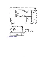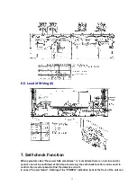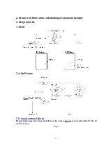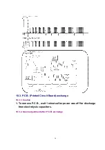
be used to narrow down the +B line.
7.1. Self-check of the microcomputer control system (bus line)
Indicaton method
Press the “ACTION” button in the control panel of the unit simultaneously with the “POWER”
button in the control panel of the unit. Hold them few seconds.
Return to he normal screen
Press any button on the unit or in the remote control.
Screen Display
Display
Ref. No.
Description
Board
MEMORY
IC002
EEPROM for Main MPU
DG
SOUND
IC2401
Sound Control
H
YUV_SW
IC4301
YUV switch
H
GC2M1
IC4501
Global Core 2 for main
DG
GC2S1
IC4502
Global Core 2 for sub
DG
EXDAC2
IC5011
EXDAC
DV
TNR1
TNR201
Tuner 1
TA
MTS
IC4205
Multiplex sound
H
EXDAC
IC8031
External I/O
DG
GC2M2
IC4501
Global Core 2 for main
DG
GC2S2
IC4502
Global Core 2 for sub
DG
PANEL
- - - - -
Panel
- - - - -
TNR2
TNR251
Tuner 2
TB
AVSW
IC4302
AV switch
H
CONV
IC3801
Convert Micom
DG
SND2
IC4203
BBE
H
HDMI
IC5003
HDMI Recelver
DV
14
Summary of Contents for TH-42PX20U/P Operating
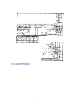
Page 9: ...6 2 Lead of Wiring 2 9 ...
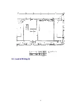
Page 10: ...6 3 Lead of Wiring 3 10 ...
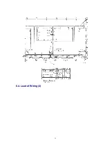
Page 11: ...6 4 Lead of Wiring 4 11 ...
Page 12: ...6 5 Lead of Wiring 5 12 ...
Page 34: ...15 2 Parts Location 2 34 ...
Page 35: ...15 3 Parts Location 3 35 ...
Page 36: ...36 ...
Page 37: ...15 4 Parts Location 4 15 5 Parts Location 5 37 ...
Page 38: ...38 ...
Page 42: ...17 2 Electrical Replacement Parts List 42 ...
Page 54: ...D12 K1KA07A00189 7P CONNECTOR 1 54 ...
Page 348: ...1 Applicable signals 4 TH 42PX20U P ...
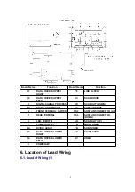
Page 353: ...6 Location of Lead Wiring 6 1 Lead of Wiring 1 9 TH 42PX20U P ...
Page 354: ...6 2 Lead of Wiring 2 10 TH 42PX20U P ...
Page 355: ...6 3 Lead of Wiring 3 11 TH 42PX20U P ...
Page 356: ...6 4 Lead of Wiring 4 12 TH 42PX20U P ...
Page 357: ...6 5 Lead of Wiring 5 13 TH 42PX20U P ...
Page 358: ...6 6 Lead of Wiring 6 14 TH 42PX20U P ...
Page 367: ...9 4 IIC mode structure following items value is sample data 23 TH 42PX20U P ...
Page 376: ...32 TH 42PX20U P ...


