background image

2/2

Setup

Screensaver

MULTI DISPLAY Setup

Set up TIMER

PRESENT TIME Setup

Screensaver

Start

Function
Mode

Side panel
Wobbling
Peak limit

Finish Time

Start Time

White bar scroll

Off

6:15

12:30

High

Off
Off

PRESENT  TIME    99:99

Screensaver

Start

Function
Mode

Side panel
Wobbling
Peak limit

Finish Time

Start Time

White bar scroll

Off

6:15

12:30

High

Off
Off

PRESENT  TIME    99:99

Screensaver

Start

Function
Mode

Side panel
Wobbling
Peak limit

Finish Time

Start Time

White bar scroll

On

6:15

12:30

High

Off
Off

PRESENT  TIME    99:99

29

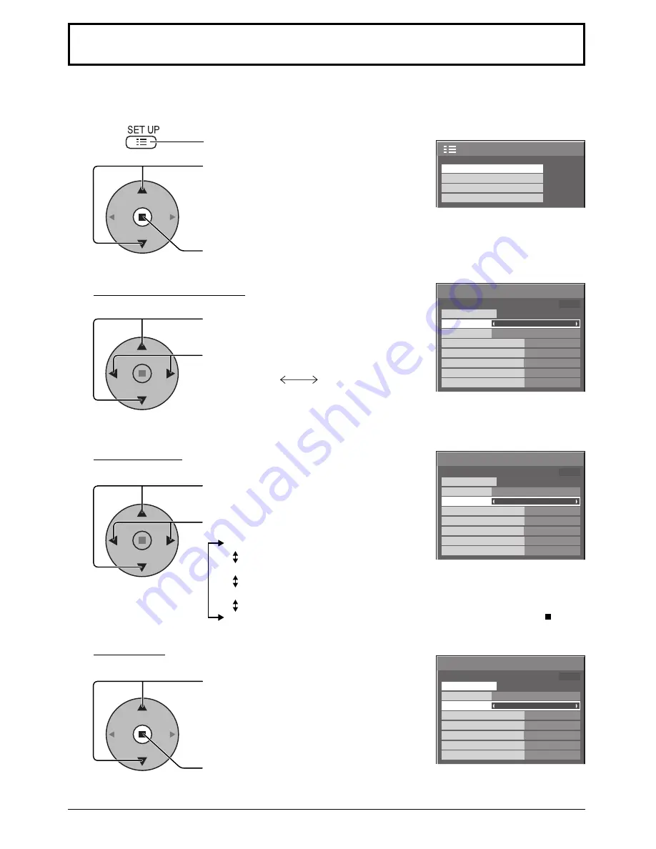
Screensaver 

(For preventing image retention)

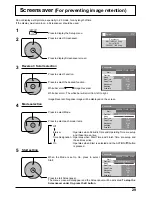
Do not display a still picture, especially in 4:3 mode, for any length of time.
If the display must remain on, a Screensaver should be used.

Reversal / Scroll selection

2

3

1

4

Press to display the Setup menu.

Press to select Screensaver.

Press to display Screensaver screen.

Press to select Function.

Press to select the desired function.

White bar scroll 

 Image Reversal 

White bar scroll : The white bar will scroll from left to right.

Image Reversal : Negative image will be displayed on the screen.

Mode selection

Start setting

5

When the Mode is set to On, press to select 
Start.

Press to start Screensaver.
The menu screen will disappear and the Screensaver will be activated. 

To stop the 

Screensaver under On, press the R button. 

Press to select Mode.

Press to select each mode items.

Off

Interval 

: Operates when Periodic Time and Operating Time are setup 

and those times arrive.

Time Designation : Operates when Start Time and Finish Time are setup and 

those times arrive.

On 

: Operates when Start is selected and the ACTION (  ) button 

is pressed.

Summary of Contents for TH-42PS10BK

Page 1: ... set and retain them for future reference Model No Operating Instructions Progressive Wide Plasma Display English The illustration shown is an image TH 42PS10BK TH 42PS10BS Model No High Definition Plasma Display TH 42PH10BK TH 42PH10BS TH 50PH10BK TH 50PH10BS TH 58PH10BK ...

Page 2: ...GB in select 38 3D Y C Filter 38 Colour system Panasonic Auto 39 Cinema reality P NR 39 Sync 40 H Freq kHz V Freq Hz 40 Options Adjustments 41 Weekly Command Timer for TH 42PH10BK S TH 50PH10BK S TH 58PH10BK 48 Shipping condition 50 Troubleshooting 51 VIDEO PC input signals 52 Command list of Weekly Command Timer 53 Specifications 54 Trademark Credits VGA is a trademark of International Business M...

Page 3: ... in this plug Shall the fuse need to be replaced please ensure that the replacement fuse has a rating of 5 amps and that it is approved by ASTA or BSI to BS1362 Check for the ASTA mark ASA or the BSI mark on the body of the fuse If the plug contains a removable fuse cover you must ensure that it is refitted when the fuse is replaced If you lose the fuse cover the plug must not be used until a repl...

Page 4: ...Board TY 42TM6G PC Input Terminal Board TY 42TM6P Composite Component Video Terminal Board TY 42TM6Y SDI Terminal Board TY FB7SD HD SDI Terminal Board TY FB9HD HDMI Terminal Board TY FB8HM Ir Through Terminal Board TY FB9RT Wireless Presentation Board TY FB10WPE TH 42PH10BK S TH 50PH10BK S TH 58PH10BK AV Terminal Box TY TB10AV Touch Panel TY TP42P8 S TH 42PS10BK S TH 42PH10BK S TY TP50P8 S TH 50PH...

Page 5: ...ks Securely insert the power supply plug as far as it will go If the plug is not fully inserted heat may be generated which could cause fire If the plug is damaged or the wall socket is loose they shall not be used Do not handle the power supply plug with wet hands Doing so may cause electric shocks Do not do anything that may damage the power cable When disconnecting the power cable pull on the p...

Page 6: ...Cleaning and maintenance The front of the display panel has been specially treated Wipe the panel surface gently using only a cleaning cloth or a soft lint free cloth If the surface is particularly dirty wipe with a soft lint free cloth which has been soaked in pure water or water in which neutral detergent has been diluted 100 times and then wipe it evenly with a dry cloth of the same type until ...

Page 7: ...rol transmitter Disposal of batteries should be in an environment friendly manner Observe the following precaution 1 Batteries shall always be replaced as a pair Always use new batteries when replacing the old set 2 Do not combine a used battery with a new one 3 Do not mix battery types example Zinc Carbon with Alkaline 4 Do not attempt to charge short circuit disassemble heat or burn used batteri...

Page 8: ...s sufficient slack in cables to minimize stress especially in the power cord firmly bind all cables with the supplied fixing band To tighten To loosen Pull Pull Push the catch AC cord fixing Notes On TH 42PH10BK S TH 50PH10BK S and TH 58PH10BK Terminal board is installed in SLOT 1 at factory shipment On TH 42PS10BK S SLOT 1 3 are all empty at factory shipment Dual Video Terminals equivalent of BNC...

Page 9: ...s no need to use an adapter for computers with DOS V compatible Mini D sub 15P terminal The computer shown in the illustration is for example purposes only Additional equipment and cables shown are not supplied with this set Do not set the horizontal and vertical scanning frequencies for PC signals which are above or below the specified frequency range Component Input is possible with the pin 1 2 ...

Page 10: ...es If multiple commands are transmitted be sure to wait for the response for the first command to come from this unit before sending the next command If an incorrect command is sent by mistake this unit will send an ER401 command back to the computer SL1A SL1B SL2A and SL2B of Command IMS are available only when a dual input terminal board is attached With the power off this display responds to PO...

Page 11: ...is unit has a terminal board equivalent to BNC Dual Video Terminal Board TY FB9BD as standard equipment 11 Connections Note Additional equipment cables and adapter plugs shown are not supplied with this set S VIDEO VCR CAMCORDER VCR Example of input signal source AV connection for TH 42PH10BK S TH 50PH10BK S TH 58PH10BK ...

Page 12: ...n screen is displayed From the second time on language selection can be done from the setup menu see page 13 Select the desired language using the or button and press the ACTION button Note Set with the remote control Buttons on the main unit are unavailable for this setting From the second time on the below screen is displayed for a while setting condition is an example Press the button on the re...

Page 13: ... the terminal board is not installed into the SLOT Select to match the signals from the source connected to the component RGB input terminals see page 38 In 2 screen display the same input mode cannot be selected for the main picture and sub picture Selecting the input signal Select the input signals to be connected by installing the optional Terminal Boards Press to select the input signal to be ...

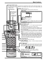
Page 14: ...e 16 INPUT button INPUT1 INPUT2 INPUT3 and PC selection see page 13 Normal Viewing Picture Setup Sound Pos Size Remote control sensor SURROUND button The surround setting switches on and off each time the SURROUND button is pressed The benefits of surround sound are enormous You can be completely enveloped in sound just as if you were at a concert hall or cinema Note The surround settings are memo...

Page 15: ...tion that darkens the screen slightly is activated to prevent image retention see page 51 this function is not the perfect solution to image retention Channel Adjustment This button cannot be used for this model Volume Adjustment Press the Volume Up or Down button to increase or decrease the sound volume level OFF TIMER button The Plasma Display can be preset to switch to stand by after a fixed pe...

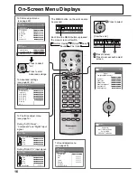
Page 16: ...ff Power management Off Auto power off Off OSD Language English UK Component RGB in select RGB Input label Power save Setup 2 2 Setup Screensaver MULTI DISPLAY Setup Set up TIMER PRESENT TIME Setup INPUT MENU ENTER VOL INPUT MENU ENTER VOL 1 2 16 On Screen Menu Displays To Pos Size adjust menu see page 19 During RGB PC input signal During AV S Video Component and Digital input signal To Sound adju...

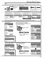
Page 17: ...l Time Designation 6 15 12 30 High Off Off PRESENT TIME 15 00 Screensaver Start Function Mode Side panel Wobbling Peak limit Operating Time Periodic Time White bar scroll Interval 12 00 3 00 High Off Off PRESENT TIME 15 00 MULTI DISPLAY Setup Location MULTI DISPLAY Setup Ratio Off 2 2 A1 INPUT MENU ENTER VOL 17 On Screen Menu Displays 2 Press to access each adjust screen Press the R button to retu...

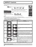
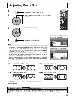
Page 18: ... size to change unexpectedly When viewing such programs it is recommended that theASPECT be set to 4 3 If adjusting the Picture V Pos V Size in Panasonic Auto with 16 9 mode the adjustment is not memorized When exiting the mode the screen will return to a former adjustment Panasonic Auto can not be selected while BNC Dual Video Terminal Board TY FB9BD is installed For an elongated image Image is e...

Page 19: ...r is received the picture position will shift up or down This picture position movement cannot be controlled by the Picture Pos Size function If adjusting the Picture V Pos V Size in Panasonic Auto with 16 9 mode the adjustment is not memorized When exiting the mode the screen will return to a former adjustment While the Pos Size display is active if either the N button on the remote control is pr...

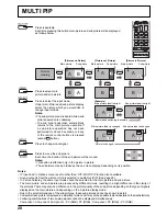
Page 20: ... lock in Options menu is set to other than Off MULTI PIP function isn t available Sound output is from the picture which is selected in Audio Out PIP See page 25 In 2 screen display the same input mode cannot be selected for the main picture and sub picture The main picture and sub picture are processed by different circuits resulting in a slight difference in the clarity of the pictures There may...

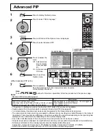
Page 21: ... the 2 picture display mode Due to the small dimensions of the sub pictures these sub pictures cannot be shown in detail Computer screen picture is displayed in a simplified format and it may not be possible to discern details on them satisfactorily Following combinations of two analog signals cannot be displayed simultaneously Component Component Component PC RGB PC RGB Component PC RGB PC RGB Re...

Page 22: ...r the ACTION button is pressed during Normalise then all adjustment values are returned to the factory settings Helpful Hint Normalise Normalisation Normal Cool Warm Press or button to switch between modes Normal For viewing in standard evening lighting environments This menu selects the normal levels of Brightness and Contrast Dynamic For viewing in brighter environments This menu selects higher ...

Page 23: ...ing of dark pictures such as night scenes and black hair Colour Less More Adjusts colour saturation Tint Reddish Greenish Adjusts for nice skin colour Sharpness Less More Adjusts picture sharpness Item Effect Details Black extension Less More Adjusts the dark shades of the image in gradation Input level Less More Adjustment of parts which are extremely bright and hard to see This cannot be adjuste...

Page 24: ... areas W B Low G Less More Adjusts the white balance for dark green areas W B Low B Less More Adjusts the white balance for dark blue areas On the remote control unit while the Advanced settings menu is displayed if either the N button is pressed at any time or the ACTION button is pressed during Normalise then all adjustment values are returned to the factory settings Helpful Hint Normalise Norma...

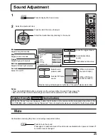
Page 25: ... Surround settings are memorized separately for each Sound Mode 2 Select to adjust each item While the Sound menu is displayed if either the N button on the remote control is pressed at any time or the ACTION button is pressed during Normalise then all adjustment values are returned to the factory settings Helpful Hint Normalise Normalisation Accentuates sharp sound Emits the original sound Normal...

Page 26: ...s This is shown in the image being displayed Return to normal display quit Digital Zoom Press to exit from the Digital Zoom The cursor will move Notes When power goes OFF including Off Timer operation Digital Zoom terminates The Digital Zoom function cannot be selected while in the following operation state Multi viewer Picture in Picture Picture out Picture Picture and Picture operation see page ...

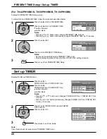
Page 27: ...f necessary Then set POWER ON Time POWER OFF Time Press to display the Setup menu Press to select Set up TIMER or PRESENT TIME Setup Press to display the Set up TIMER screen or PRESENT TIME Setup screen 1 2 Display the PRESENT TIME Setup screen To setup PRESENT TIME follow the procedure described below PRESENT TIME Setup 1 2 Press to select PRESENT TIME Press to setup PRESENT TIME button Forward b...

Page 28: ...R ON Time POWER OFF Time by 15 minutes Press to select POWER ON Function POWER OFF Function Press to select On Press twice to exit from Setup 1 2 3 Note Timer function will not work unless PRESENT TIME is set Display the Set up TIMER screen Display the PRESENT TIME Setup screen To setup DAY and PRESENT TIME follow the procedure described below 1 2 Press to select DAY or PRESENT TIME Press to setup...

Page 29: ...ould be used Reversal Scroll selection 2 3 1 4 Press to display the Setup menu Press to select Screensaver Press to display Screensaver screen Press to select Function Press to select the desired function White bar scroll Image Reversal White bar scroll The white bar will scroll from left to right Image Reversal Negative image will be displayed on the screen Mode selection Start setting 5 When the...

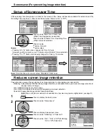
Page 30: ...hite bar scroll Off 6 15 12 30 High Off Off PRESENT TIME 99 99 30 Screensaver For preventing image retention Setup of Screensaver Time After selecting Time Designation or Interval the relevant Time Setup will become available for selection and the Operating Time may be set Time cannot be set when Mode is On or Off Press to select Start Time Finish Time When Time Designation is selected Press to se...

Page 31: ...remain on the side panels either side of the display field To reduce the risk of such an image retention illuminate the side panels Display the Screensaver screen Refer to the previous page operation guide steps 1 and 2 Notes To reduce the occurrence of image retention set the Side panel to High The side panels may flash alternate black white depending on the picture being shown on the screen Usin...

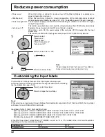
Page 32: ...e is no signal When this is set to On the power supply of the unit goes Off 10 minutes after the input signals stop This function is effective for input signals except input from PC Mini D sub terminal Press to select Input label Press to change the Input label Customizing the Input labels This function can change the label of the Input signal to be displayed Select the input signal which you woul...

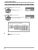
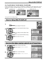
Page 33: ... across all screens For this mode of operation each plasma display has to be set up with a Display number to determine its location group of 4 2 2 F group of 9 3 3 F group of 16 4 4 F How to Setup MULTI DISPLAY Press to select the MULTI DISPLAY Setup Press to display the MULTI DISPLAY Setup menu 1 2 3 Press to select the MULTI DISPLAY Setup Press to select On or Off Press to display the Setup menu...

Page 34: ...I DISPLAY Press to select Ratio 2nd step Press to select 2 2 2 2 F 3 3 3 3F 4 4 4 4F How to set the display location number for each Plasma Display 4 Press to select Location Press to select the required arrangement number A1 D4 Refer to the following 5 Display Number locations for each arrangement 2 2 F 3 3 F 4 4 F Press twice to exit from Setup 6 ...

Page 35: ...ng up Plasma Displays in groups for example as illustrated below an enlarged picture may be displayed across all screens For this mode of operation each plasma display has to be set up with a Display number to determine its location Example Press to display the Setup menu How to Setup MULTI DISPLAY group of 16 4 4 group of 4 2 2 group of 9 3 3 1 2 3 Setup for MULTI DISPLAY see page 36 for more dis...

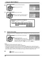
Page 36: ...is turned on with a time lag to reduce the power load Notes This setting is valid when MULTI DISPLAY Setup is On During this function is working the power indicator is blinking green This function also works when the power recovers from failure or after plugging off and in again the power cord If unplugging and plugging the power cord while the unit is in standby mode and the power is being suppli...

Page 37: ...e effect as pressing the buttons at the same time Notes Set the Remote ID On to operate the ID remote control If Remote ID is set to On you can use the remote control without identical ID number during option menu display see page 43 46 The ID remote control cannot be used when ID select is set to anything other than 0 and the remote control ID is not the same as the ID select number see page 43 4...

Page 38: ...match the signals from the source connected to the Component RGB input terminals Y PB PR signals Component R G B HD VD signals RGB 1 2 Press to display the Setup menu Press to select the Component RGB in select Press to select the desired input signal Component RGB Press to exit from adjust mode 3D Y C Filter For NTSC AV images Select Signal from the Setup menu duringAV S Video input signal Signal...

Page 39: ...r set the system to match the format of the input signal Cinema reality P NR Press to select Cinema reality or P NR Press to set On Off Press to exit from adjust mode Cinema reality When on the display attempts to reproduce a more natural interpretation of sources such as movie pictures which are recorded at 24 frames per second If the picture is not stable turn the setting to off Note When On thi...

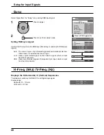
Page 40: ... RGB input this setting is valid only for RGB input signal Auto The H and V sync or synchronized signal are automatically selected If both input it is selected the H and V sync on G Uses a synchronized signal on the Video G signal which is input from the G connector VBS Uses a synchronized signal of Composite Sync input which is input from the HD connector Displays the H Horizontal V Vertical freq...

Page 41: ...on Disable Disables the Off timer function Note When Disable is set the Off timer is cancelled Onscreen display On Off On Displays all the following on screen Power on display Input signal switch display No signal display Mute and the remaining time of off timer after was pressed Off Hides all the items above from view Initial INPUT Off PC INPUT1 INPUT2 INPUT3 Adjusts the input signal when the uni...

Page 42: ...adjusted signal is displayed see page 13 Signal can be displayed when the Terminal board is installed Input switch can be used when this is set to Off In two screen display mode if anything other than Off is set the value will be fixed as the value input in the single screen display mode When a dual input terminal board is attached A or B is displayed depending on the selected input signal Ex INPU...

Page 43: ...ote ID or Serial ID Set value range 0 100 Standard value 0 Remote ID Off On Off Disables ID remote control functions You can use normal remote control operations On Enable ID remote control functions Serial ID Off On Sets the panel ID Control Off Disables external control by the ID On Enables the external control by the ID Item Effect Adjustments Slot Power Off Auto On Off Power is not transmitted...

Page 44: ...ms above from view Initial INPUT Off PC INPUT1 INPUT2 INPUT3 Adjusts the input signal when the unit is turned on Notes Only the adjusted signal is displayed see page 13 Signal can be displayed when the Terminal board is installed This menu is available only when INPUT lock is Off When a dual input terminal board is attached A or B is displayed depending on the selected input signal Ex INPUT1A INPU...

Page 45: ... Only the adjusted signal is displayed see page 13 Signal can be displayed when the Terminal board is installed Input switch can be used when this is set to Off In two screen display mode if anything other than Off is set the value will be fixed as the value input in the single screen display mode When a dual input terminal board is attached A or B is displayed depending on the selected input sign...

Page 46: ...ID Control Off Disables external control by the ID On Enables the external control by the ID Display size Off On Adjusts the image display size on screen Off Sets the normal image display size on screen On Sets the image display size approximately 95 of the normal image display Off On Notes This setting is valid only when the input signals are as follows NTSC PAL SECAM M NTSC PAL60 PAL M PAL N BNC...

Page 47: ...o the slot power only when main power is on On Power is transmitted to the slot power when main power is on or in the standby state Note In some cases power is transmitted to the slot power when main power is on or in the standby state regardless of the slot power setting V Installation Off On Off Sets fan to the horizontal installation mode On Sets fan to the vertical installation mode Notes This...

Page 48: ...rogram number 48 You can set 7 day timer programming by setting time and command Note Before setting Weekly Command Timer set PRESENT TIME Setup see page 27 Press to select Function Press to select On Note When Function is set to On Set up TIMER see page 28 is unavailable and Interval Time Designation in Mode of Screensaver see page 29 cannot be selected 1 Press to select a day Press to select a p...

Page 49: ...ss to select a command number 6 Press to select Time Command Press to set each item Time Set the time to execute a command program Pressing or button once changes Time 1 minute Pressing or button continuously changes Time by 15 minutes Command Select a command to execute at the set time This unit has 64 commands to set see page 53 Notes Command is performed in order of execution time regardless of...

Page 50: ...nu Press to select OSD Language Press and hold till the SHIPPING menu is displayed Press to select YES Press to confirm from the unit 1 Press the MENU button till the Setup menu is displayed 2 Press the Volume Up or Down button to select OSD Language 3 Press and hold the ENTER button till the SHIPPING menu is displayed 4 Press the Volume Up or Down button to select YES 5 Press the ENTER button and...

Page 51: ... audio depending on the type of input signal However this is not a malfunction Plasma Display panel Symptoms Check The screen darkens slightly whenbrightpictureswithminimal movements are shown The screen will darken slightly when photos still images of a computer or other pictures with minimal movements are shown for an extended period This is done to reduce image retention on the screen and the s...

Page 52: ...5 Hz 37 50 75 00 31 5 18 640 480 85 Hz 43 27 85 01 36 0 19 852 480 60 Hz 31 47 59 94 33 54 2 20 800 600 56 Hz 35 16 56 25 36 0 21 800 600 60 Hz 37 88 60 32 40 0 22 800 600 72 Hz 48 08 72 19 50 0 23 800 600 75 Hz 46 88 75 00 49 5 24 800 600 85 Hz 53 67 85 06 56 25 25 1 024 768 60 Hz 48 36 60 00 65 0 26 1 024 768 70 Hz 56 48 70 07 75 0 27 1 024 768 75 Hz 60 02 75 03 78 75 28 1 024 768 85 Hz 68 68 85...

Page 53: ...e mode Picture in Picture 36 DWA POP Dual Picture mode Picture out Picture 37 DWA SWP Swap main picture and sub picture when PIP mode 38 DWA TWN Dual Picture mode Picture and Picture 39 IMS PC1 Input select PC1 Main Picture when PIP mode 40 IMS SL1 Input select SLOT1 Main Picture when PIP mode 41 IMS SL1A Input select SLOT1A Main Picture when PIP mode 42 IMS SL1B Input select SLOT1B Main Picture w...

Page 54: ...Hz Connection terminals PC IN HIGH DENSITY MINI D SUB 15PIN B PB CB R PR CR HD VD VBS use HD port AUDIO IN M3 JACK Y or G with sync 1 0 Vp p 75 Ω Y or G without sync 0 7 Vp p 75 Ω 0 7 Vp p 75 Ω 0 7 Vp p 75 Ω 1 0 5 0 Vp p high impedance with picture 1 0 Vp p high impedance without picture 0 3 Vp p high impedance 0 5 Vrms high impedance SERIAL EXTERNAL CONTROL TERMINAL D SUB 9PIN RS 232C COMPATIBLE ...

Page 55: ...r System NTSC PAL PAL60 SECAM Modified NTSC Scanning format 525 480 60i 60p 625 575 50i 50p 750 720 60p 50p 1125 1080 60i 50i 24p 25p 30p 24sF SMPTE274M 1250 1080 50i PC signals VGA SVGA XGA SXGA UXGA compressed Horizontal scanning frequency 15 110 kHz Vertical scanning frequency 48 120 Hz Connection terminals AV IN VIDEO IN BNC S VIDEO IN MINI DIN 4PIN AUDIO IN RCA PIN JACK 4 1 0 Vp p 75 Ω Y 1 0 ...

Page 56: ...01344 476540 or customer care panasonic co uk for more details Information on Disposal for Users of Waste Electrical Electronic Equipment private households This symbol on the products and or accompanying documents means that used electrical and electronic products should not be mixed with general household waste For proper treatment recovery and recycling please take these products to designated ...

Reviews: